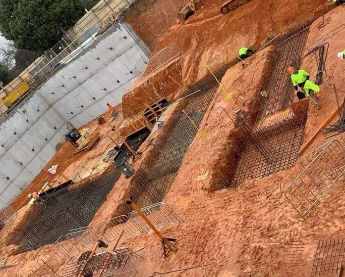
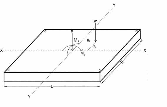
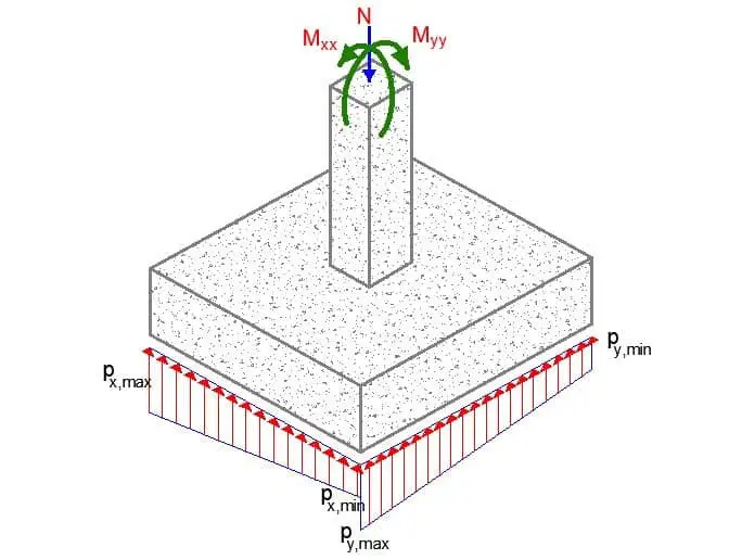
A biaxial eccentrically loaded pad footing occurs when the column transmitting load to the foundation is subjected to compressive axial force and bending moment in the two principal axes. As a result of the biaxial bending, two eccentricities ex and ey of the axial load occur on the pad footing, thereby leading to non-uniform pressure distribution on the foundation. The effects of such non-uniform pressure distribution must be accounted for during the geotechnical and structural design of the pad foundation.
This article will consider the geotechnical and structural design of a biaxial eccentrically loaded pad footing. The footing for a single column may be made square in plan, but where there is a large moment acting about only one axis it may be more economical to have a rectangular base.
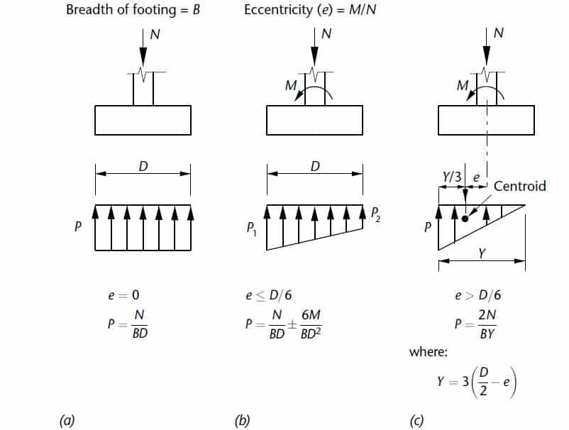
When a bending moment M and axial force N are acting on a pad foundation, the pressures are given by the equation for axial load plus bending. This condition is valid provided there is positive contact between the pad base and the ground along the complete length D of the footing so that;
p = N/BD ± My/I
where I is the second-moment area of the base about the axis of bending and y is the distance from the axis to where the pressure is being calculated.
Substituting for I = BD3/12 and y = D/2, the maximum pressure is;
pmax = N/BD + 6M/BD2
and the minimum pressure is;
pmin = N/BD – 6M/BD2
For biaxially loaded footings, this pressure must be verified in both directions, and the maximum pressure should not exceed the allowable bearing capacity of the soil. Furthermore, the reinforcement design must also be carried out in both directions.
Design Example of Biaxial Eccentrically Loaded Pad Footing
A 1500 x 1500mm pad foundation is subjected to the following loads from a 250 mm x 250 mm square column;
Permanent load axial load; FGz1 = 650.0 kN
Variable laxial load; FQz1 = 135.0 kN
Permanent moment in x; MGx1 = 25.0 kNm
Permanent moment in y; MGy1 = 21.0 kNm
Variable moment in x; MQx1 = 13.0 kNm
Variable moment in y; MQy1 = 11.0 kNm
The design is to be done in accordance with EN1997-1:2004 incorporating Corrigendum dated February 2009 and the UK National Annex incorporating Corrigendum No.1
Pad foundation details
Length of foundation; Lx = 1500 mm
Width of foundation; Ly = 1500 mm
Foundation area; A = Lx × Ly = 2.250 m2
Depth of foundation (thickness of footing); h = 500 mm
Depth of soil over foundation; hsoil = 600 mm
Level of water; hwater = 0 mm
Density of water; γwater = 9.8 kN/m3
Density of concrete; γconc = 25.0 kN/m3
Column details
Length of column; lx1 = 250 mm
Width of column; ly1 = 250 mm
position in x-axis; x1 = 750 mm
position in y-axis; y1 = 750 mm
Library item: Column details output
Soil properties
Density of soil; γsoil = 18.0 kN/m3
Characteristic cohesion; c’k = 15 kN/m2
Characteristic effective shear resistance angle; φ’k = 25 deg
Characteristic friction angle; δk = 20 deg
Foundation loads
Permanent surcharge load; FGsur = 5.0 kN/m2
Self weight; Fswt = h × γconc = 12.5 kN/m2
Soil weight; Fsoil = hsoil × γsoil = 10.8 kN/m2
Column loads
Permanent load in z; FGz1 = 650.0 kN
Variable load in z; FQz1 = 135.0 kN
Permanent moment in x; MGx1 = 25.0 kNm
Permanent moment in y; MGy1 = 21.0 kNm
Variable moment in x; MQx1 = 13.0 kNm
Variable moment in y; MQy1 = 11.0 kNm
Design Approach 1 (DA 1) – Combination 1
Partial factors on actions – Combination1
Partial factor set; A1
Permanent unfavourable action – Table A.3; γG = 1.35
Permanent favourable action – Table A.3; γGf = 1.00
Variable unfavourable action – Table A.3; γQ = 1.50
Variable favourable action – Table A.3; γQf = 0.00
Partial factors for soil parameters – Combination1
Soil factor set; M1
Angle of shearing resistance – Table A.4; γφ’ = 1.00
Effective cohesion – Table A.4; γc’ = 1.00
Weight density – Table A.4; γg = 1.00
Partial factors for spread foundations – Combination1
Resistance factor set; R1
Bearing – Table A.5; γR.v = 1.00
Sliding – Table A.5; γR.h = 1.00
Bearing Resistance
Forces on foundation
Force in z-axis; Fdz = γG × [A × (Fswt + Fsoil + FGsur) + FGz1] + γQFQz1 = 1166.0 kN
Moments on foundation
Moment in x-axis;
Mdx = γG × (A × (Fswt + Fsoil + FGsur) × Lx/2 + FGz1x1) + γGMGx1 + γQFQz1x1 + γQMQx1 = 927.7 kNm
Moment in y-axis;
Mdy = γG × (A × (Fswt + Fsoil + FGsur) × Ly/2 + FGz1y1) + γGMGy1 + γQFQz1y1 + γQMQy1 = 919.3 kNm
Eccentricity of base reaction
Eccentricity of base reaction in x-axis;
ex = Mdx / Fdz – Lx / 2 = 46 mm
Eccentricity of base reaction in y-axis;
ey = Mdy / Fdz – Ly / 2 = 38 mm
Effective area of base
Effective length;
L’x = Lx – 2 × ex = 1409 mm
Effective width;
L’y = Ly – 2 × ey = 1423 mm
Effective area;
A’ = L’x × L’y = 2.005 m2
Pad base pressure
Design base pressure; fdz = Fdz / A’ = 581.6 kN/m2
Design angle of shearing resistance; φ’d = tan-1(tan(φ’k) / γφ’) = 25.000 deg
Design effective cohesion; c’d = c’k / γc’ = 15.000 kN/m2
Effective overburden pressure;
q = (h + hsoil) × γsoil – hwater × γwater = 19.800 kN/m2
Design effective overburden pressure;
q’ = q / γg = 19.800 kN/m2
Bearing resistance factors;
Nq = Exp(π × tan(φ’d)) × [tan(45 deg + φ’d / 2)]2 = 10.662
Nc = (Nq – 1) × cot(φ’d) = 20.721
Nγ = 2 × (Nq – 1) × tan(φ’d) = 9.011
Foundation shape factors;
sq = 1 + (L’x / L’y) × sin(φ’d) = 1.418
sγ = 1 – 0.3 × (L’x / L’y) = 0.703
sc = (sq × Nq – 1) / (Nq – 1) = 1.462
Load inclination factors;
H = 0.0 kN
my = [2 + (L’y / L’x)] / [1 + (L’y / L’x)] = 1.497
mx = [2 + (L’x / L’y)] / [1 + (L’x / L’y)] = 1.503
m = mx = 1.503
iq = [1 – H / (Fdz + A’ × c’d × cot(φ’d))]m = 1.000
iγ = [1 – H / (Fdz + A’ × c’d × cot(φ’d))]m + 1 = 1.000
ic = iq – (1 – iq) / (Nc × tan(φ’d)) = 1.000
Ultimate bearing capacity;
nf = c’dNcscic + q’Nqsqiq + 0.5γsoilL’xNγsγiγ = 834.0 kN/m2
PASS – Ultimate bearing capacity exceeds design base pressure
Design Approach 1 (DA 1) – Combination 2
Partial factors on actions – Combination2
Partial factor set; A2
Permanent unfavourable action – Table A.3; γG = 1.00
Permanent favourable action – Table A.3; γGf = 1.00
Variable unfavourable action – Table A.3; γQ = 1.30
Variable favourable action – Table A.3; γQf = 0.00
Partial factors for soil parameters – Combination2
Soil factor set; M2
Angle of shearing resistance – Table A.4; γφ’ = 1.25
Effective cohesion – Table A.4; γc’ = 1.25
Weight density – Table A.4; γg = 1.00
Partial factors for spread foundations – Combination2
Resistance factor set; R1
Bearing – Table A.5; γR.v = 1.00
Sliding – Table A.5; γR.h = 1.00
Bearing resistance (Section 6.5.2)
Forces on foundation
Force in z-axis;
Fdz = γG × (A × (Fswt + Fsoil + FGsur) + FGz1) + γQFQz1 = 889.2 kN
Moments on foundation
Moment in x-axis;
Mdx = γG × (A × (Fswt + Fsoil + FGsur) × Lx/2 + FGz1 × x1) + γGMGx1 + γQFQz1x1 + γQMQx1 = 708.8 kNm
Moment in y-axis;
Mdy = γG × (A × (Fswt + Fsoil + FGsur) × Ly/2 + FGz1 × y1) + γGMGy1 + γQFQz1y1 + γQMQy1 = 702.2 kNm
Eccentricity of base reaction
Eccentricity of base reaction in x-axis;
ex = Mdx / Fdz – (Lx /2) = 47 mm
Eccentricity of base reaction in y-axis;
ey = Mdy / Fdz – (Ly/2) = 40 mm
Effective area of base
Effective length;
L’x = Lx – 2ex = 1406 mm
Effective area;
A’ = L’x × L’y = 1.997 m2
Effective width;
L’y = Ly – 2ey = 1421 mm
Pad base pressure
Design base pressure; fdz = Fdz / A’ = 445.3 kN/m2
Ultimate bearing capacity under drained conditions (Annex D.4)
Design angle of shearing resistance;
φ’d = tan-1(tan(φ’k) / γf’) = 20.458 deg
Design effective cohesion;
c’d = c’k / γc’ = 12.000 kN/m2
Effective overburden pressure;
q = (h + hsoil) × γsoil – hwater × γwater = 19.800 kN/m2
Design effective overburden pressure;
q’ = q/γg = 19.800 kN/m2
Bearing resistance factors;
Nq = Exp(π × tan(φ’d)) × (tan(45 deg + φ’d / 2))2 = 6.698
Nc = (Nq – 1) × cot(φ’d) = 15.273
Nγ = 2 × (Nq – 1) × tan(φ’d) = 4.251
Foundation shape factors;
sq = 1 + (L’x / L’y) × sin(φ’d) = 1.346
sγ = 1 – 0.3 × (L’x / L’y) = 0.703
sc = (sq × Nq – 1) / (Nq – 1) = 1.407
Load inclination factors;
H = 0.0 kN
my = [2 + (L’y / L’x)] / [1 + (L’y / L’x)] = 1.497
mx = [2 + (L’x / L’y)] / [1 + (L’x / L’y)] = 1.503
m = mx = 1.503
iq = [1 – H / (Fdz + A’ × c’d × cot(φ’d))]m = 1.000
iγ = [1 – H / (Fdz + A’ × c’d × cot(φ’d))]m + 1 = 1.000
ic = iq – (1 – iq) / (Nc × tan(φ’d)) = 1.000
Ultimate bearing capacity;
nf = c’dNcscic + q’Nqsqiq + 0.5 γsoilL’xNγ sg iγ = 474.1 kN/m2
PASS – Ultimate bearing capacity exceeds design base pressure
Foundation design (EN1992-1-1:2004)
In accordance with EN1992-1-1:2004 incorporating Corrigendum dated January 2008 and the UK National Annex incorporating National Amendment No.1
Concrete details
Concrete strength class; C25/30
Characteristic compressive cylinder strength; fck = 25 N/mm2
Characteristic compressive cube strength; fck,cube = 30 N/mm2
Mean value of compressive cylinder strength;fcm = fck + 8 N/mm2 = 33 N/mm2
Mean value of axial tensile strength; fctm = 0.3 N/mm2 × (fck)2/3 = 2.6 N/mm2
5% fractile of axial tensile strength;fctk,0.05 = 0.7 × fctm = 1.8 N/mm2
Secant modulus of elasticity of concrete; Ecm = 22 kN/mm2 × [fcm/10]0.3 = 31476 N/mm2
Partial factor for concrete (Table 2.1N); γC = 1.50
Compressive strength coefficient (cl.3.1.6(1)); acc = 0.85
Design compressive concrete strength (exp.3.15); fcd = acc × (fck / γC) = 14.2 N/mm2
Tens.strength coeff.for plain concrete (cl.12.3.1(1)); act,pl = 0.80
Des.tens.strength for plain concrete (exp.12.1); fctd,pl = act,pl × (fctk,0.05 / γC) = 1.0 N/mm2
Maximum aggregate size; hagg = 20 mm
Ultimate strain – Table 3.1; εcu2 = 0.0035
Shortening strain – Table 3.1;εcu3 = 0.0035
Effective compression zone height factor; λ = 0.80
Effective strength factor; h = 1.00
Bending coefficient k1; K1 = 0.40
Bending coefficient k2; K2 = 1.00 × (0.6 + 0.0014/εcu2) =1.00
Bending coefficient k3; K3 =0.40
Bending coefficient k4; K4 =1.00 × (0.6 + 0.0014/εcu2) = 1.00
Reinforcement details
Characteristic yield strength of reinforcement; fyk = 500 N/mm2
Modulus of elasticity of reinforcement; Es = 210000 N/mm2
Partial factor for reinforcing steel (Table 2.1N); γS = 1.15
Design yield strength of reinforcement; fyd = fyk / γS = 435 N/mm2
Nominal cover to reinforcement; cnom = 50 mm
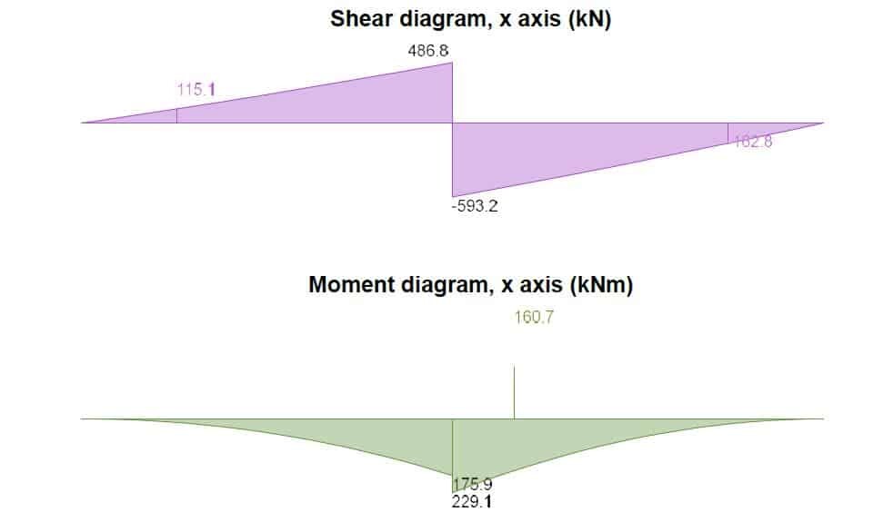
Rectangular section in flexure (x-axis)
Design bending moment; MEd.x.max = 160.7 kNm
Depth to tension reinforcement; d = h – cnom – φx.bot / 2 = 444 mm
K = MEd.x.max / (Ly × d2 × fck) = 0.022
K’ = (2 × h × acc/γC) × (1 – λ(d – K1)/(2K2)) × (λ(d – K1)/(2K2))
K’ = 0.207
K’ > K – No compression reinforcement is required
Lever arm; z = min(0.5 + 0.5 × (1 – 2K / (h × acc /γc))0.5, 0.95) × d = 422 mm
Depth of neutral axis; x = 2.5(d – z) = 55 mm
Area of tension reinforcement required;
Asx.bot.req = MEd.x.max / (fydz) = 876 mm2
Tension reinforcement provided;
10Y12@155 c/c bottom (Asx.bot.prov = 1131 mm2)
Minimum area of reinforcement (exp.9.1N);
As.min = max(0.26 × fctm / fyk, 0.0013) × Ly × d = 888 mm2
Maximum area of reinforcement (cl.9.2.1.1(3));
As.max = 0.04 × Ly × d = 26640 mm2
PASS – Area of reinforcement provided is greater than area of reinforcement required
Rectangular section in shear (x-axis)
Design shear force;
abs(VEd.x.min) = 162.8 kN
CRd,c = 0.18 /γC = 0.120
k = min(1 + √(200 mm / d), 2) = 1.680
Longitudinal reinforcement ratio;
ρl = min(Asx.bot.prov / (Ly × d), 0.02) = 0.002
vmin = 0.035k3/2 × fck0.5 = 0.381 N/mm2
Design shear resistance (exp.6.2a & 6.2b);
VRd.c = max(CRd.c × k × (100 N2/mm4 × ρl × fck)1/3, vmin) × Ly × d
VRd.c = 247 kN
PASS – Design shear resistance exceeds design shear force
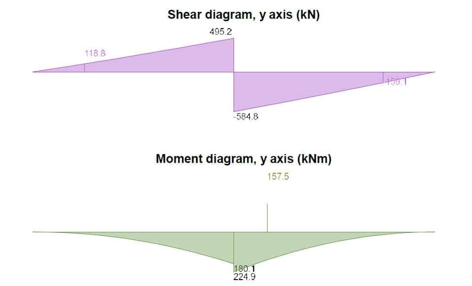
Rectangular section in flexure (y-axis)
Design bending moment;
MEd.y.max = 157.5 kNm
Depth to tension reinforcement;
d = h – cnom – fx.bot – φy.bot / 2 = 432 mm
K = MEd.y.max / (Lx × d2 × fck) = 0.02
K’ = (2h × acc/γC) × (1 – λ × (d – K1)/(2K2)) × (λ × (d – K1)/(2K2))
K’ = 0.207
K’ > K – No compression reinforcement is required
Lever arm;
z = min(0.5 + 0.5 × (1 – 2K / (h × acc/γC))0.5, 0.95) × d = 410 mm
Depth of neutral axis;
x = 2.5(d – z) = 54 mm
Area of tension reinforcement required;
Asy.bot.req = MEd.y.max / (fydz) = 883 mm2
Tension reinforcement provided;
12Y12@125 c/c Asy.bot.prov = 1357 mm2
Minimum area of reinforcement (exp.9.1N);
As.min = max(0.26fctm / fyk, 0.0013) × Lx × d = 864 mm2
Maximum area of reinforcement (cl.9.2.1.1(3));
As.max = 0.04 × Lx × d = 25920 mm2
PASS – Area of reinforcement provided is greater than the area of reinforcement required
Crack control
Limiting crack width; wmax = 0.3 mm
Variable load factor (EN1990 – Table A1.1); y2 = 0.3
Serviceability bending moment; Msls.y.max = 99 kNm
Tensile stress in reinforcement; ss = Msls.y.max / (Asy.bot.prov × z) = 177.8 N/mm2
Load duration factor; kt = 0.4
Effective depth of concrete in tension;
hc.ef = min(2.5 × (h – d), (h – x) / 3, h/2) = 149 mm
Effective area of concrete in tension;
Ac.eff = hc.ef × Lx = 223000 mm2
Mean value of concrete tensile strength;
fct.eff = fctm = 2.6 N/mm2
Reinforcement ratio;
ρp.eff = Asy.bot.prov / Ac.eff = 0.006
Modular ratio; ae = Es / Ecm = 6.672
Bond property coefficient; k1 = 0.8
Strain distribution coefficient; k2 = 0.5
k3 = 3.4
k4 = 0.425
Maximum crack spacing (exp.7.11);
sr.max = k3 × (cnom + fx.bot) + k1k2k4 × φy.bot / ρp.eff = 546 mm
Maximum crack width (exp.7.8);
wk = sr.max × max([ss – kt × (fct.eff / ρp.eff) × (1 + ae × ρp.eff)] / Es, 0.6 × ss / Es) = 0.277 mm
PASS – Maximum crack width is less than limiting crack width
Rectangular section in shear (y-axis)
Design shear force; abs(VEd.y.min) = 159.1 kN
CRd,c = 0.18/γC = 0.120
k = min(1 + √(200 mm / d), 2) = 1.680
Longitudinal reinforcement ratio;
rl = min(Asy.bot.prov / (Lx × d), 0.02) = 0.002
vmin = 0.035k3/2 × fck0.5 = 0.381 N/mm2
Design shear resistance (exp.6.2a & 6.2b);
VRd.c = max(CRd.c × k × (100 × rl × fck)1/3, vmin) × Lx × d
VRd.c = 247 kN
PASS – Design shear resistance exceeds design shear force
Punching shear
Strength reduction factor (exp 6.6N); v = 0.6[1 – fck / 250] = 0.540
Average depth to reinforcement; d = 438 mm
Maximum punching shear resistance (cl.6.4.5(3)); vRd.max = 0.5vfcd = 3.825 N/mm2
k = min(1 + √(200 mm / d), 2) = 1.676
Longitudinal reinforcement ratio (cl.6.4.4(1));
rlx = Asx.bot.prov / (Ly × d) = 0.002
rly = Asy.bot.prov / (Lx × d) = 0.002
rl = min(√(rlx × rly), 0.02) = 0.002
CRd,c = 0.18 / gC =0.120
vmin = 0.035 k3/2 × fck0.5 = 0.380 N/mm2
Design punching shear resistance (exp.6.47);
vRd.c = max(CRd.c k (100rlfck)1/3, vmin) = 0.380 N/mm2
Design punching shear resistance at 1d (exp. 6.50);
vRd.c1 = (2d/d)vRd.c = 0.759 N/mm2
Punching shear perimeter at column face
Punching shear perimeter; u0 = 1000 mm
Area within punching shear perimeter; A0 = 0.063 m2
Maximum punching shear force; VEd.max = 1046 kN
Punching shear stress factor (fig 6.21N); β = 1.500
Maximum punching shear stress (exp 6.38);
vEd.max = β VEd.max / (u0 × d) = 3.582 N/mm2
PASS – Maximum punching shear resistance exceeds maximum punching shear stress
Punching shear perimeter at 1d from column face
Punching shear perimeter; u1 = 3752 mm
Area within punching shear perimeter; A1 = 1.103 m2
Design punching shear force; VEd.1 = 480.5 kN
Punching shear stress factor (fig 6.21N); β = 1.500
Design punching shear stress (exp 6.38); vEd.1 = βVEd.1 / (u1d) = 0.439 N/mm2
PASS – Design punching shear resistance exceeds increased design punching shear stress
Punching shear perimeter at 2d from column face
Punching shear perimeter; u2 = 63 mm
Area within punching shear perimeter; A2 = 2.250 m2
Design punching shear force; VEd.2 = 0 kN
Punching shear stress factor (fig 6.21N); β = 1.500
Design punching shear stress (exp 6.38); vEd.2 = βVEd.2 / (u2 × d) = 0.001 N/mm2
PASS – Design punching shear resistance exceeds design punching shear stress

