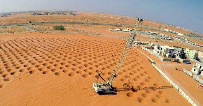
Luis Menard developed dynamic compaction (DC), also known as dynamic deep compaction, in the middle of the 1960s. However, there are claims that the technique was used more than a thousand years before. In this ground improvement technique, a heavy weight is dropped on the ground’s surface to compact soils to depths of up to 40 feet (12.5 metres).
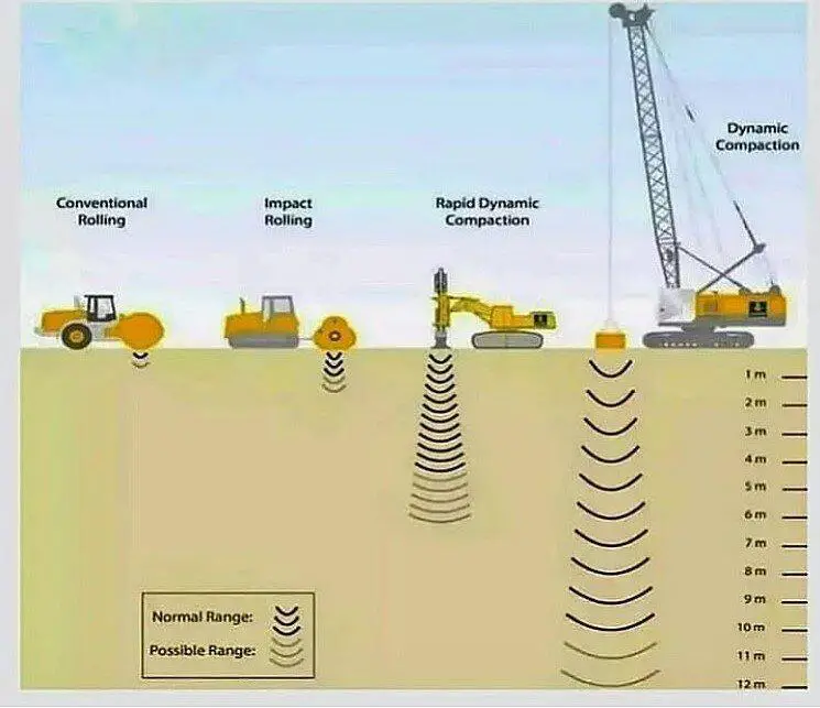
The technique is utilised to reduce settlements in foundations, reduce seismic subsidence and liquefaction potential, permit development on fills, densify refuse dumps, enhance mining spoils, and reduce settlements in collapsible soils.
Applicable Soil Types for Dynamic Compaction
The most suitable types of soil for dynamic compaction are granular, permeable soils. In cohesive soils, the compaction energy tends to be absorbed by fine soil particles, which reduces the technique’s effectiveness. Table 1 shows the anticipated improvement for various soil types.
| Soil Description | Expected Improvement | Typical Energy Required (tons ft/cf) |
| Gravel and sand <10% silt, no clay | Excellent | 2.0 – 2.5 |
| Sand with 10—80% silt and <20% clay, PI < 8 | Moderate if dry; minimal if moist | 2.5-3.5 |
| Finer-grained soil with pI > 8 | Not applicable | – |
| Landfill | Excellent | 6-11 |
Note that for Table 1 above, Energy = (drop height x weight x number of drops)/soil volume to be compacted; 1 ton ft/ft3 = 94.1 kJ/m3.
For the procedure to be successful, the groundwater table must be at least 6 feet (1.8 metres) below the working surface. Sand or stone columns have been built using dynamic compaction in organic soils by repeatedly filling the crater with the material and forcing the column through the organic layer.
Equipment
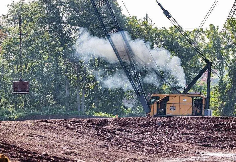
Although specifically designed rigs have been made, the weight is typically dropped using a cycle-duty crane. Standard cranes are often not designed to handle high-cycle dynamic loading, so in order to maintain a safe working environment, the cranes must be in good condition and constantly maintained and inspected while performing the operation.
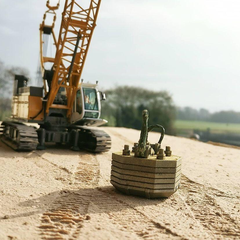
The crane is often set up with enough boom to drop the weight from heights of 50 to 100 ft (15.4 to 30.8 m) and only one rope to let it almost “free fall,” maximising the force of the weight hitting the soil. The weight to be lowered must be less than the crane’s and cable’s safe single-line capability. Typically weights range from 10 to 30 tons (90 to 270 kN) and are constructed of steel to withstand the repetitive dynamic forces.
Procedure
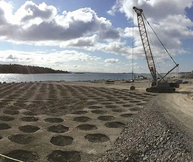
Lifting and dropping a weight repeatedly till it hits the ground surface is the major technique for dynamic compaction. The primary drop locations are normally laid out in a grid of 10 to 20 feet (3.1 to 6.2 metres), with a secondary pass placed at each of the primary pass’s midpoints. Prior to doing subsequent drops at that place, the crater is filled with granular material once it has reached a depth of 3 to 4 ft (about 1 m).
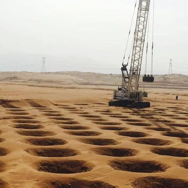
Large soil vibrations are generated by the operation, which may negatively affect surrounding existing structures. In particular, structures within 500 feet (154 metres) of the locations of the intended drops should be examined for their vibration sensitivity and their antecedent conditions. Monitoring the vibrations when carrying out dynamic compaction is also advisable. If dynamic compaction is intended to be carried out within 200 feet (61.5 metres) of an existing structure, extreme caution and close observation should be made.
Materials
A clean, freely draining granular earth is often used to fill the craters left behind by the operation. Sandy soils can be treated by using a backfill made of sand. Finer-grained soils or landfills are frequently treated with a crushed stone backfill.
Design
An examination of the proposed construction and the current subsurface conditions will serve as the starting point for the design (bearing capacity, settlement, liquefaction, etc.). The minimal values required to deliver the required performance are then determined using the same study with the improved soil characteristics (e.g., SPT N value, etc.). The next step is to calculate the vertical and lateral extent of improved soil required to deliver the desired performance.
The square root of the energy from a single drop (weight times drop height) applied to the ground surface determines the depth of the effect. Dr. Robert Lucas created the correlation shown below using data collected in the field:
D = k(W x H)0.5
where;
D is the maximum influence depth in meters beneath the ground surface,
W is the weight in metric tons (9 kN) of the object being dropped, and
H is the drop height in meters above the ground surface.
The constant k varies with soil type and is between 0.3 and 0.7, with lower values for finer-grained soils.
Even though the largest depth of improvement predicted by this method is in the upper two-thirds, the improvement gradually decreases until it reaches zero in the bottom third. The degree of improvement attained within this zone is increased by landing strikes repeatedly at the same spot. However, when the rate of improvement falls, there comes a moment when the benefits become less valuable.
Table 1 lists the anticipated range of unit energy needed to reach this goal. Treatment of landfills is helpful in minimising voids, but it has minimal impact on the biodegradation of components in the future. As a result, treatment of landfills is normally only allowed in areas designated for planned roadways and pavement, not for structures. The soils are loose within 3 to 4 feet (1 m) of the surface once dynamic compaction is finished. A low-energy “ironing pass,” which typically entails dropping the same weight from a height of 10 to 15 feet (3.0 to 4.5 metres) over the entire surface area, is used to compact the surface soils.
Quality control and quality assurance
Penetration testing is used in the majority of applications to evaluate improvement. Penetration testing is challenging in construction waste or landfills, however large-scale load experiments using fill mounds or shear wave velocity tests can be carried out. To measure the progress made and make necessary adjustments, a test area might be treated at the start of the programme. To identify “soft” sections of the site that need more treatment, the depth of the craters can also be measured. When adequate improvement is attained, the decrease in penetration with further drops serves as a signal.
References
Hussin J. D. (2006): ‘Methods of soft ground improvement’ in ‘The Foundation Engineering Handbook’ Edited by Gunaratne M. Taylor and Francis USA.

