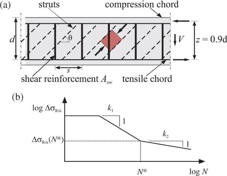
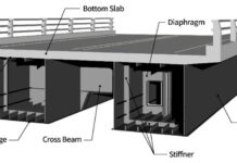
Deck slabs of bridges are likely to be among the elements that are influenced by fatigue verification calculations the most. This is due to the high live load to dead load ratio that these slabs have. Tests, on the other hand, have shown that the actual stress ranges in the reinforcement in these are significantly lower than what is suggested by the standard elastic calculations. As a result of this, the NA to BS EN 1992-2 identifies situations in which fatigue assessment is not necessary and gives regulations that are on the safe side.
The failure of a structure due to repeated loadings that are smaller than a single static force that exceeds the material’s strength is known as Fatigue. Fatigue occurs when a material fails due to direct tension or compression, torsion, bending, or a combination of these actions.

Since reinforced concrete is a composite material, it can fail due to fatigue in a variety of ways. Failure is frequently the result of a variety of reasons, and failure types can vary quite significantly. The concrete, the reinforcement, and the bond between the materials might all fail locally.
Compressive fatigue failure in reinforced concrete is referred to as ductile because cracks might appear in the concrete long before the structure falls. Because the crack propagation rate in the reinforcement at the end is rather fast, tensile fatigue failure in reinforced concrete has a more brittle behaviour.
According to clause 6.8.1 of BS EN 1992-2, a fatigue verification is generally not necessary for the following structures and structural elements:
- Footbridges, with the exception of structural components very sensitive to wind action.
- Buried arch and frame structures with a minimum earth cover of 1 m and 1.5 m for road and railway bridges.
- Foundations.
- Piers and columns which are not rigidly connected to superstructures.
- Retaining walls of embankments for roads and railways.
- Abutments of road and railway bridges which are not rigidly connected to superstructures, except the slabs of hollow abutments.
- Prestressing and reinforcing steel, in regions where, under the frequent load combination of actions and Pk only compressive stresses occur at the extreme concrete fibres.
Furthermore, in the case of road bridges, fatigue verification is not required for the local effects of wheel loads given directly to a slab that spans across beams or webs, provided that the following conditions are met:
- The slab does not contain welded reinforcement or reinforcement couplers.
- The clear span to overall depth ratio of the slab does not exceed 18.
- The slab acts compositely with its supporting beams or webs.
- Either:
- the slab also acts compositely with transverse diaphragms; or
- the width of the slab perpendicular to its span exceeds three times its clear span.
In Eurocode there are two alternative methods by which fatigue verification can be calculated for bridges;
- the λ-Coefficient Method and
- the Cumulative Damage Method.
Both approaches take into account the loading during the course of a structure’s lifetime. The λ-Coefficient Method is a simplified method that uses a single load model amplified by several coefficients. The Cumulative Damage Method is a complicated model that takes into account the load history in greater detail. The λ-Coefficient Method simply evaluates if the building meets the code’s requirements, whereas the Cumulative Damage Method derives a fatigue damage factor that indicates the structure’s actual damage in relation to the design fatigue life.

Internal Forces and Stresses for Fatigue Verification
According to clause 6.8.2 of BS EN 1992-2, the calculation of stress for fatigue verification must be based on the assumption of cracked cross-sections, which must be done while ignoring the tensile strength of the concrete and satisfying compatibility of strains. The influence of the varied bond behaviour of prestressing steel and reinforcing steel must be taken into account by increasing the stress range in the reinforcing steel computed under the assumption of a perfect bond by the factor, η, which is given by:
η = (As + Ap)/[(As + Ap) × √ξ(ϕs/ϕp)]
where:
As = area of reinforcing steel
Ap = area of prestressing tendon or tendons
ϕs = largest diameter of reinforcement
ϕp = diameter or equivalent diameter of prestressing steel
= 1.6 √Ap for bundles
= 1.75 ϕwire for single 7-wire strands where ϕwire is the wire diameter
= 1.20 ϕwire for single 3-wire strands where ϕwire is the wire diameter
ξ = ratio of bond strength between bonded tendons and ribbed steel in concrete. The value is subject to the relevant European Technical Approval. In the absence of this the values given in Table 1 may be used.
| Prestressing steel | ξ (pre-tensioned) | ξ (Bonded, post-tensioned) ≤ C50/60 | ξ (Bonded, post-tensioned) ≥ C70/85 |
| Smooth bars and wires | Not Applicable | 0.3 | 0.15 |
| Strands | 0.6 | 0.5 | 0.25 |
| Indented wires | 0.7 | 0.6 | 0.30 |
| Ribbed bars | 0.8 | 0.7 | 0.50 |
For intermediate values between C50/60 and C70/85, interpolation may be used.
Verification of Concrete under Compression or Shear
According to clause 7.6.2 of PD 6687-2, it is doubtful that National Authorities will have the S–N curves that are necessary to carry out a fatigue verification of concrete while it is being subjected to compression or shear. In the absence of such data, the simplified technique that is outlined in BS EN 1992-2, Annex NN may be utilised for railway bridges; however, there is no equivalent alternative available for highway bridges.
σc,max/fcd,fat ≤ 0.5 + 0.45(σc,min/fcd,fat)
where;
σc,max = maximum compressive stress at a fibre under the frequent load combination (compression measured positive)
σc,min = minimum compressive stress at the same fibre where σc,max occurs. If σc,min is a tensile stress, then σc,min should be taken as zero
fcd,fat = design fatigue strength of concrete = 0.85 βcc(t0) fcd (1 – fck/250)
fcd = fck / 1.5
βcc(t0) = coefficient for concrete strength at first load application = exp{s[1 – (28/t0)0.5]}
where;
t0 = time of the start of the cyclic loading on concrete in days
s = 0.2 for cement of strength Classes CEM 42.5R, CEM 52.5N and CEM 52.5R (Class R)
= 0.25 for cement of strength Classes CEM 32.5R, CEM 42.5 (Class N)
= 0.38 for cement of strength Class CEM 32.5 (Class S)
The maximum value for the ratio σc,max / fcd,fat is given in Table 2.
| Concrete Strength | σc,max / fcd,fat |
| fck ≤ 50 MPa | ≤ 0.9 |
| fck > 50 MPa | ≤ 0.8 |

For members not requiring design shear reinforcement for the ultimate limit state it may be assumed that the concrete resists fatigue due to shear effects where the following apply:
for VEd,min/VEd,max ≥ 0:
|VEd,max|/|VRd,c| ≤ 0.5 + 0.45|VEd,min|/|VRd,c|
≤ 0.9 up to C50/60
≤ 0.8 greater than C55/67
for VEd,min/VEd,max < 0:
|VEd,max|/|VRd,c| ≤ 0.5 |VEd,min|/|VRd,c|
where;
VEd,max = design value of the maximum applied shear force under frequent load combination
VEd,min = is the design value of the minimum applied shear force under frequent load combination in the cross-section where VEd,max occurs
VRd,c = design value for shear resistance
Limiting Stress Range for Reinforcement under Tension
Adequate fatigue resistance may be assumed for reinforcing bars under tension if the stress range under the frequent cyclic load combined with the basic combination does not exceed 70 MPa for unwelded bars and 35 MPa for welded bars.
For UK highway bridges, the values in Tables 12.3 and 12.4 may be used for straight reinforcement. These are based on bars conforming to BS 4449. For bars not conforming to BS 4449, the rules for bars > 16 mm diameter should be used for all sizes unless the ranges for bars ≤ 16 mm diameter can be justified.
| Span (m) | Adjacent spans loaded (Bars ≤ 16 mm) | Adjacent spans loaded (Bars > 16 mm) | Alternate spans loaded (Bars ≤ 16 mm) | Alternate spans loaded (Bars > 16 mm) |
| ≤ 3.5 | 150 | 115 | 210 | 160 |
| 5 | 125 | 95 | 175 | 135 |
| 10 | 110 | 85 | 175 | 135 |
| 20 | 110 | 85 | 140 | 110 |
| 30 -50 | 90 | 70 | 110 | 85 |
| 100 | 115 | 90 | 135 | 105 |
| ≥ 200 | 190 | 145 | 200 | 155 |
For Tables 3 and 4, intermediate values can be interpolated.
| Span (m) | (Bars ≤ 16 mm) | (Bars > 16 mm) |
| ≤ 3.5 | 210 | 160 |
| 5 | 120 | 90 |
| ≥ 10 | 70 | 55 |
Full fatigue checks are to be carried out using the ‘damage equivalent stress range’ approach, following the instructions given in Annex NN of BS EN 1992-2, if the stress range limitations exceed the values specified in Tables 3 and 4 (e.g. for reinforcement over the pier). The stress ranges are derived using the ‘Fatigue Load Model 3’, which simulates a four-axle vehicle weighing 48 tonnes total. This weight is increased to 84 tonnes for intermediate supports and 67 tonnes for other locations in Annex NN.


Very Good information.