The immediate or elastic settlement of pile groups, denoted by ρi and the long-term consolidation settlement, denoted by ρc, both contribute to the total settling of a pile group in clay. Equation (1) can be used as a general rule to calculate the elastic settlement for a flexible foundation at the level of the ground surface;
ρi = qn × 2B × (1 – v2)/Eu × Ip ——– (1)
where ρi is the settlement at the centre of the flexible loaded area, qn is the net foundation pressure, B is the width of an equivalent foundation flexible raft, v is the undrained Poisson’s ratio for clay (generally taken as equal to 0.5), Ip is an influence factor, and Eu is the deformation modulus for the undrained loading conditions.
The values of Ip are dependent on the ratio H/B of the depth of the compressible soil layer to the width of the pile group, as well as the ratio L/B of the length of the group to its width. The values of Ip and, consequently, the immediate settlement of a surface foundation can be obtained through the use of curves that were established by Steinbrenner and published by Terzaghi (1943).
These curves can be found in Figure 1 of this article. To calculate the elastic settlement of pile groups, the use of Fox’s correction curves (1948) is required in order to obtain the immediate settlement of a raft foundation that is equivalent to the pile group.
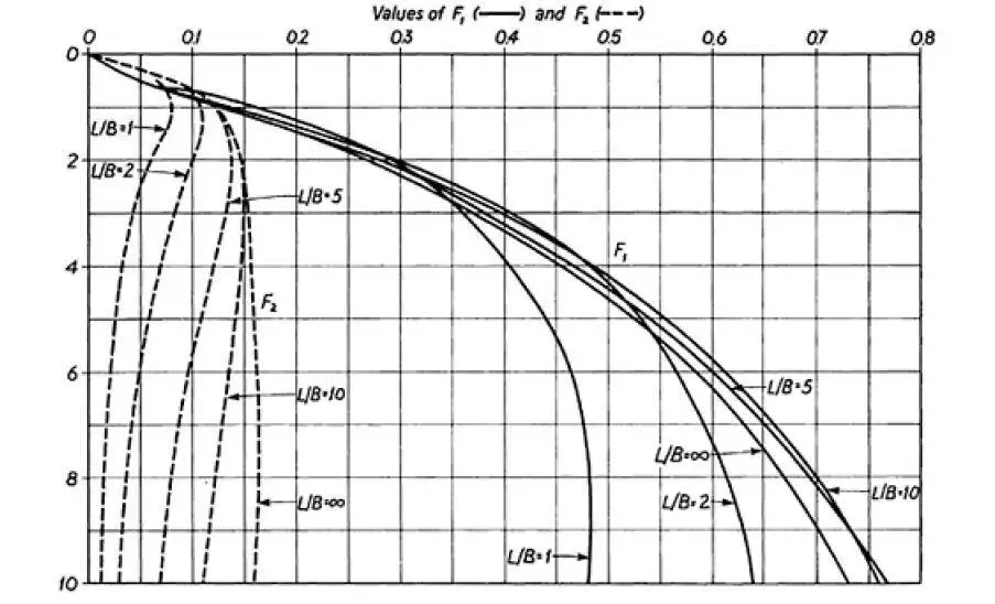
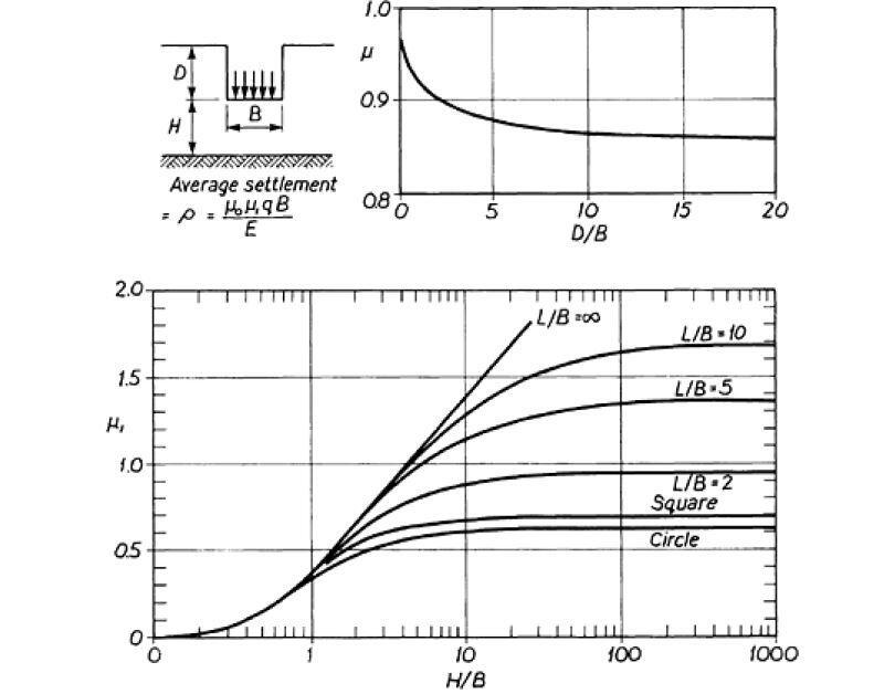
To obtain the average immediate settlement of a foundation at a depth D below the surface where the deformation modulus is reasonably constant with depth, it will be found to be more convenient to use the influence factors of Christian and Carrier (1978). In general, this will be the case where the deformation modulus is reasonably constant with depth.
Average settlement ρi = μiμ0qnB/Eu ——– (2)
In the equation (2), it was assumed that Poisson’s ratio was equal to 0.5. Figure 2 shows the factors μi and μ0, both of which are associated with the depth of the equivalent raft, the thickness of the compressible soil layer, and the length/width ratio of the equivalent raft foundation.
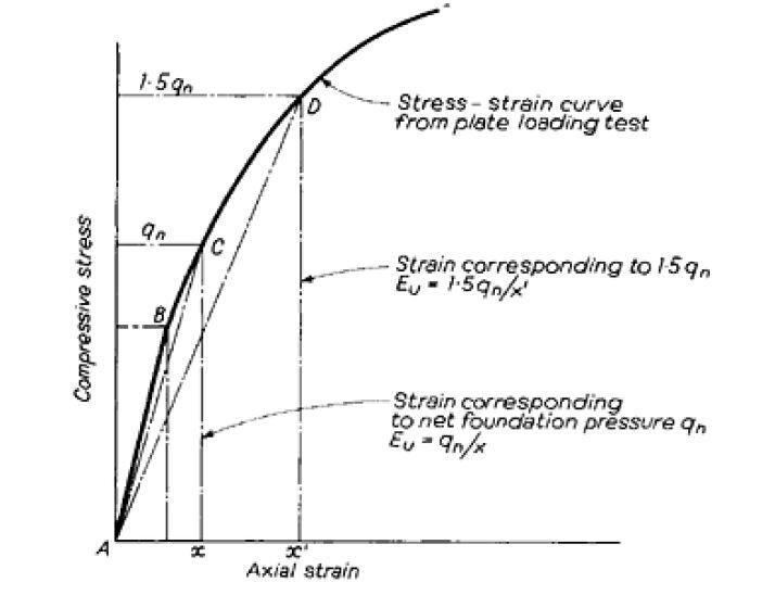
The value of the deformation modulus Eu can be determined by analysing the stress-strain curve that is produced when compressive loading is applied to the soil while the conditions are undrained. Only when the stress level is relatively low (shown by the line AB in Figure 3) does a curve of this type show purely elastic behaviour, which requires the use of a modulus of elasticity.
It is possible that the immediate settlement will be underestimated due to the fact that (Young’s modulus) corresponds to the straight-line portion. The standard procedure is to draw a secant AC to the stress-strain curve that corresponds to a compressive stress that is equal to the net foundation pressure at the base of the equivalent block foundation.
The secant AD can be drawn at a compressive stress of 1.5 or any other suitable multiple of the foundation pressure for a more conservative approach. Following this, one can calculate the deformation modulus Eu, as shown in Figure 3.
As a result of sample disturbance, unreasonably low modulus values are obtained from stress-strain curves produced from conventional unconfined or triaxial compression tests in the laboratory. These results are not representative of the material’s true behaviour. Plate bearing tests carried out in boreholes or trial pits, as well as field testing carried out with a pressuremeter or Camkometer, provide the most reliable data for calculating modulus values.
Another possibility is that Eu is connected to the clay’s undrained shearing strength cu. According to Butler (1975), the relationship Eu = 400cu for London clay is a reasonable compromise between divergent data representing, on the one hand, the relationship established from laboratory testing, and on the other hand, the observations of the settlement of full-scale structures.
Recent years have seen the development of apparatus for obtaining piston-driven tube samples of stiff clays, as well as improvements in methods for coring weak rocks. Therefore, samples that have been subjected to a relatively minor disturbance can be provided for laboratory testing to obtain modulus values. There is apparatus available that can measure very small strains during uniaxial or triaxial compression tests, which can then be utilised to derive small strain modulus values.
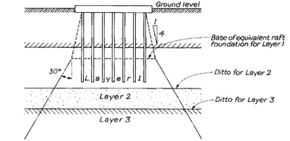
In layered soils with different values of the deformation modulus Eu in each layer or in soils which show a progressively increasing modulus with increases in depth, the strata below the base of the equivalent raft are divided into a number of representative horizontal layers, and an average value of Eu is assigned to each layer.
This ensures that the values of the deformation modulus Eu are consistent across the entire profile of the soil. The values for the dimensions L and B in Figure 2 are derived from the hypothesis that the load is distributed across the surface of each layer at an angle of thirty degrees with respect to the edges of the equivalent raft (Figure 4). After that, the total settlement of the piled foundation can be calculated as the sum of the average settlements for each soil layer that were determined using Equation 2.
The assumption that the deformation modulus remains the same with depth is the basis for the influence values presented in Figure 1. Calculations that are based on a constant modulus, on the other hand, give inflated estimates of the amount of settlement that will occur.
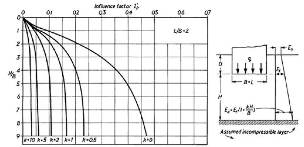
This is because the modulus increases with depth in the majority of natural soil and rock formations. Butler (1974) developed a method for settlement calculations for the conditions of a deformation modulus increasing linearly with depth within a layer of finite thickness. This method was used for determining the amount that a layer would settle. The following equation will give you the value of the modulus at a depth z below the level of the foundation:
Eu = Ef(1 + kz/B) ——– (3)
and
ρi = qnBI’p/Eu ——– (4)
where Ef represents the modulus of deformation at foundation level (the base of the equivalent raft), and ρi represents the settlement at the corner of the loaded area in the equation. In order to calculate the value of k, first plot the measured values of Eu against depth, and then draw a straight line through the points that are plotted. This will give you the values you need to substitute into equation 3.
In situations in which a plot of undrained shear strength versus depth has been obtained, the Eu vs depth line can be derived from the empirical relationships given earlier in this paragraph.
After you have determined k, you can use Butler’s curves, which are presented in Figure 5, to determine the appropriate factor for I’p. These are for different ratios of L/B at the level of the equivalent raft, and they are applicable for a compressible layer thickness that is not greater than 9B. The curves have been constructed on the basis of the assumption that an undrained condition will have a Poisson’s ratio of 0.5; this is so that the load can be applied immediately.
In situations in which the pile group covers a large area and is, as a result, relatively flexible, it is possible that it will be necessary to calculate the settlements at the corners in addition to those in the area’s centre.
Consolidation Settlement of Pile Groups
The results of oedometer tests carried out on clay samples in the laboratory are used as the basis for the calculation of the consolidation settlement ρc. The pressure-to-voids ratio curves that were obtained from these tests are what are used to calculate the volume compressibility coefficient, denoted by the symbol mv.
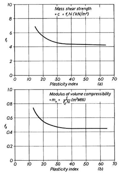
It may be difficult to obtain satisfactory undisturbed samples for oedometer testing in hard glacial tills or in rocks that have been highly weathered and weakened by weathering. If the results of standard penetration tests are available, then the values of mv (as well as cu) can be obtained from the empirical relationships established by Stroud (1975) and shown in Figure 6.
Once a representative value of mv has been obtained for each soil layer that is being stressed by the pile group, the oedometer settlement ρoed for this layer at the centre of the loaded area can be calculated using the equation;
ρoed = μdmv × σz × H ——– (5)
where μd is a depth factor, σz is the average effective vertical stress imposed on the soil layer due to the net foundation pressure qn at the base of the equivalent raft foundation and H is the thickness of the soil layer. The depth factor is obtained from Fox’s correction curves.
The oedometer settlement must now be corrected to obtain the field value of the consolidation settlement. The correction is made by applying a ‘geological factor’ μg to the oedometer settlement, where;
ρc = μg × ρoed ——– (6)
Published values of μg have been based on comparisons of the settlement of actual structures with computations made from laboratory oedometer tests. Values established by Skempton and Bjerrum (1975) are shown in Table 1.
| Type of clay | μg value |
| Very sensitive clays (soft alluvial, estuarine and marine clays) | 1.0 – 1.2 |
| Normally-consolidated clays | 0.7 – 1.0 |
| Over-consolidated clays (London clay, Weald, Kimmeridge, Oxford and Lias clays) | 0.5 – 0.7 |
| Heavily over-consolidated clays (unweathered glacial till, Keuper Marl) | 0.2 – 0.5 |
After this, the total settlement of the pile group is determined by adding together the immediate and consolidation settlements that were calculated for each individual layer. A gradual decrease in compressibility with depth is a typical example of this phenomenon. When this occurs, the stressed zone beneath the pile group is segmented into a number of distinct horizontal layers.
The value of the modulus of elasticity (mv) for each of these layers is obtained by plotting the mv value against the depth, which is based on the results of the laboratory oedometer tests. At the level where the vertical stress has decreased to one tenth of qn, the level at which the base of the lowest layer is determined to be is chosen.
When calculating the total consolidation settlements for each layer, the depth factor, denoted by d, is multiplied by that total. It does not apply to the immediate settlement if that settlement has already been computed based on the factors shown in Figure 5.
If a pile group is topped by a deep rigid cap or if it is used to support a rigid superstructure, then the pile group can be considered to be equivalent to a rigid block foundation that has a uniform settlement. This is because both of these conditions ensure that the pile group remains in its original position.
To calculate the value of the latter, a “rigidity factor” is applied to the consolidation settlement that was obtained from the equivalent flexible raft foundation. The immediate settlement can be calculated using Equation 2. This immediate settlement is the same as the average settlement that is given by a rigid foundation. The value of 0.8 for the rigidity factor is widely accepted as being appropriate.
Thus;
Settlement of rigid pile group/Settlement of flexible pile group = 0.8
It is possible, for the purposes of this condition, to consider a pile group that is composed of a number of small clusters or individual piles connected by ground beams or by a flexible ground floor slab to be equivalent to a flexible raft foundation at depth.
This is the case if the pile group is connected by ground beams. According to the calculations described above, the consolidation settlements that occurred at the corners of the piled area make up approximately one-half of the settlement that occurred in the centre of the group.
The use of Equation 1, with the substitution of a deformation modulus obtained for loading under drained conditions, is yet another method for estimating the total settlement of a structure that is resting on an over-consolidated clay.
This modulus has been given the name Ev‘, and it can be found at the bottom of Equation 1, where it stands in place of Eu. It roughly corresponds to the value of 1/mv. When used to calculate consolidation settlements, the equation does not adhere to strict validity standards because it assumes a material that is both homogenous and elastic.
However, when applied to over-consolidated clays for which the settlements are relatively small, it has been observed through experience that the method gives predictions that are reasonably reliable. The success of utilising the method is dependent on the collection of sufficient data correlating the observed settlements of structures with the determinations of from plate loading tests and laboratory tests on good undisturbed samples of clay. This is necessary for a successful outcome.
In his analysis of the settlement of structures on over-consolidated clays, Butler (1974) related Ev‘ to the undrained cohesion cu and determined that the relationship for London clay is Ev‘ = 130Cu.
In the settlement analysis of a group of piles, it is better to adopt an approach that is more rational, which is to consider immediate settlements and consolidation settlements separately. This appropriately takes into account the effects that time has had on the location as well as its geological history. The prediction of consolidation settlements based on oedometer tests conducted in the laboratory has been found to lead to reasonably accurate results, provided that a sufficient number of good undisturbed samples have been obtained at the site investigation stage.
The adoption of the method that is based on the total settlement deformation modulus is contingent upon the collection of adequate observational data, first regarding the relationship between the undrained shearing strength and the deformation modulus, and secondly regarding the actual settlement of structures from which the relationships can be checked.
The adoption of this method is dependent upon the collection of adequate observational data. It is highly unlikely that accurate results can be obtained from triaxial compression tests carried out in the lab, so any attempt to do so is likely to end in failure. The modulus can be determined most accurately using the Eu/cu and relationship formulas, which need to be derived from plate bearing tests that have been competently carried out and field observations of settlement.
The reader is directed to a report written by Padfield and Sharrock (1983) for CIRIA that contains a general discussion on the subject of the settlement of foundations on clays. According to what they have found, the immediate settlement is approximately equal to 0.5 to 0.6 times the oedometer settlement, while the consolidation settlement, is approximately equal to 0.4 to 0.5 times the oedometer settlement. This is true for stiff overconsolidated clays. When it comes to normally consolidated soft clays, the immediate settlement is roughly equivalent to 0.1 times the oedometer settlement, and the consolidation settlement is roughly equivalent to the oedometer settlement.
The steps in making a settlement analysis of a pile group in, or transmitting stress to, a cohesive soil can be summarized as follows.
- For the required length of pile, and form of pile bearing (i.e. friction pile or end-bearing pile), draw the equivalent flexible raft foundation represented by the group.
- From the results of field or laboratory tests assign values to Eu and mv for each soil layer significantly stressed by the equivalent raft.
- Calculate the immediate settlement of ρi of each soil layer using equation 2, and assuming a spread of load of 30° from the vertical to obtain qn at the surface of each layer (Figure 4). Alternatively calculate on the assumption of a linearly increasing modulus.
- Calculate the consolidation settlement ρc for each soil layer from Equations 5 and 6, using relevant charts to obtain the vertical stress at the centre of each layer.
- Apply a rigidity factor to obtain the average settlement for a rigid pile group.
The consolidation settlement calculated as described above is the final settlement after a period of some months or years after the completion of loading. It is rarely necessary to calculate the movement at intermediate times, i.e. to establish the time settlement curve, since in most cases the movement is virtually complete after a period of a very few years and it is only the final settlement which is of interest to the structural engineer. If time effects are of significance, however, the procedure for obtaining the time-settlement curve can be obtained from standard works of reference on soil mechanics.
References
- TERZAGHI, K (1943). Theoretical Soil Mechanics, John Wiley, New York, p. 425.
- FOX, E.N. (1948). The mean elastic settlement of a uniformly-loaded area at a depth below the ground surface, Proceedings of the 2nd International Conference, ISSMFE, Rotterdam, Vol. 1, pp. 129–32.
- CHRISTIAN, J.T. and CARRIER, W.D. (1978). Janbu, Bjerrum and Kjaernsli’s chart reinterpreted, Canadian Geotechnical Journal, Vol. 15, pp. 123–8.
- BUTLER, F.G. (1974). General report and state-of-the-art review, Session 3, Proceedings of the Conference on Settlement of Structures, Cambridge, Pentech Press, London, pp. 531–78.
- STROUD, M.A. (1975) The standard penetration test in insensitive clays, Proceedings of the European Symposium on Penetration Testing, Stockholm, Vol. 2, pp. 367–75.
- SKEMPTON, A.W. and BJERRUM, L. A (1957). contribution to the settlement analysis of foundations on clay , Geotechnique, Vol. 7, No. 4, pp. 168–78.
- PADFIELD, C.J. and SHARROCK, M.J. (1983). Settlement of structures on clay soils, Construction Industry Research and Information Association (CIRIA), Special Publication 27, 1983.
Feature Image:
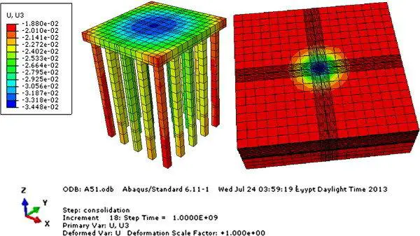
Ata A., Badrawi E., Nabil M. (2015): Numerical analysis of unconnected piled raft with cushion. Ain Shams Engineering Journal, 6(2):421-428 https://doi.org/10.1016/j.asej.2014.11.002.

