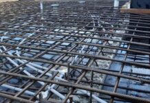
Reinforced concrete structures rely on the effective transfer of stress between steel reinforcement bars. Lap splices, where two reinforcement bars overlap within the concrete element, are a common method to achieve this continuity. Lapping of reinforcement is a frequent occurrence in construction due to supply length limitations, construction joints, stage construction, and ease of handling of rebars.
Therefore, determining the appropriate lap length is important for ensuring structural integrity and preventing premature failure. This article discusses how to calculate the lap length for reinforcements in concrete structures.
Factors Influencing Lap Length
Several factors influence the required lap length:
- Reinforcement diameter (Φ): Larger diameter bars require longer lap lengths for effective stress transfer.
- Concrete grade (fck): Higher concrete strength allows for shorter lap lengths due to improved bond characteristics.
- Reinforcement yield strength (fyk): Higher yield strength steel requires longer lap lengths to develop its full capacity.
- Concrete cover: The thickness of the concrete cover influences the bond transfer and hence, the anchorage length.
- Bond condition: The orientation of the reinforcement (straight or bent) and the concrete cover can lead to a good or poor bond condition which can influence the anchorage length of reinforcements.
- Confinement conditions: The presence of stirrups or ties around the lap splice can significantly reduce the required lap length.
- Type of Lap Splice: Standard lap splices require longer lengths compared to hooked or welded lap splices.
Methods of Calculating Lap Length
Different design codes and standards provide methods for calculating lap length. Here’s a breakdown of two common approaches:
1. Basic Lap Length Formula:
This simplified method often serves as a preliminary estimate:
Lap Length (L) = 50d
Where:
d = Reinforcement diameter (mm)
This formula assumes standard lap splices in normal concrete conditions.
2. Code-Based Calculations:
Detailed calculations are typically based on specific design codes like Eurocode 2 (EC2) or ACI 318. These codes provide equations and tables that consider various factors influencing lap length:
EC2 Method:
EC2 employs a formula that incorporates the bar diameter, concrete grade, steel yield strength, and a factor accounting for the percentage of bars lapped in one section.
ACI 318 Method:
ACI 318 provides tables with tabulated lap lengths based on bar diameter, concrete strength, and type of splice (standard, hooked, or welded).
Note:
- Minimum Lap Length: Codes often specify minimum lap lengths regardless of calculations.
- Development Length: Lap length should be greater than or equal to the development length of the bar, which is the minimum length required for the bar to develop its full yield strength in the surrounding concrete.
- Longitudinal Spacing of Bars: The spacing between lapped bars within the overlap zone can affect the required lap length.
- Lightweight Concrete: Adjustments are often necessary for lap lengths in lightweight concrete due to its lower bond strength.
Anchorage Length
Apart from the lapping of steel reinforcements, reinforcing bars should be well anchored so that the bond forces are safely transmitted to the concrete to avoid longitudinal cracking or spalling. The length of rebar required to achieve adequate transfer of forces is known as the anchorage length. Transverse reinforcement shall be provided if necessary.
Apart from straight bars, other shapes that are specified in the code are;
(a) standard bend,
(b) standard hook, and
(c) standard loop.
The detailing rules and the equivalent anchorage length for each of these standard shapes are defined in EN1992-1-1 Figure 8.1. Types of anchorage are shown in the figure below (Figure 8.1 EC2).
For bent bars, the basic tension anchorage length is measured along the centreline of the bar from the section in question to the end of the bar, where:
lbd = α1 α2 α3 α4 α5 lb,req ≥ lb,min ———— (1)
where;
lb,min is the minimum anchorage length taken as follows:
In tension, the greatest of 0.3lb,rqd or 10ϕ or 100mm
In compression, the greatest of 0.6lb,rqd or 10ϕ or 100mm
lb,rqd is the basic anchorage length given by;
lb,rqd = (ϕ/4) σsd/fbd ————– (2)
Where;
σsd = The design strength in the bar (take 0.87fyk)
fbd = The design ultimate bond stress (for ribbed bars = 2.25η1 η2 fctd)
fctd = Design concrete tensile strength
fctd = 0.21fck(2/3) for fck ≤ 50 N/mm2
η1 is a coefficient related to the quality of the bond condition and the position of the bar during concreting
η1 = 1.0 when ‘good’ conditions are obtained and
η1 = 0.7 for all other cases and for bars in structural elements built with slip-forms, unless it can be shown that ‘good’ bond conditions exist
η2 is related to the bar diameter:
η2 = 1.0 for φ ≤ 32 mm
η2 = (132 – φ)/100 for φ > 32 mm
‘Good’ bond conditions are applicable when any of the following conditions are fulfilled:
(a) Vertical bars or almost vertical bars inclined at an angle 45° ≤ α ≤ 90° from the horizontal,
(b) bars that are located up to 250 mm from the bottom of the formwork for elements with height h ≤ 600 mm, or
(c) bars that are located at least 300 mm from the free surface during concreting for elements with height h > 600 mm.
‘Poor’ bond conditions are applicable for all other cases and also for bars in structural elements built with slip-forms, unless it can be shown that ‘good’ bond conditions exist. The different bond regions are shown in the figure above that is reproduced from EN1992-1-1 Figure 8.2.
α1 is for the effect of the form of the bars assuming adequate cover.
α2 is for the effect of concrete minimum cover.
α3 is for the effect of confinement by transverse reinforcement
α4 is for the influence of one or more welded transverse bars ( φt > 0.6φ) along the design anchorage length lbd
α5 is for the effect of the pressure transverse to the plane of splitting along the design anchorage length.
The values of these coefficients can be adequately obtained by following the Table below;
l0,min = max{0.3α6 lb,rqd; 15ϕ; 200}
α6 = √(ρ1/25) but between 1.0 and 1.5
where ρ1 is the % of reinforcement lapped within 0.65l0 from the centre of the lap
Values of α1, α2, α3 and α5 may be taken as for the calculation of anchorage length but for the calculation of α3, ΣAst,min should be taken as 1.0As(σsd/fyd), with As = area of one lapped bar.
SOLVED EXAMPLE FOR ANCHORAGE LENGTH
Calculate the design tension anchorage length of T16mm bar (fyk = 460 N/mm2, concrete cover = 35 mm, Concrete cylinder strength fck = 25 N/mm2) for;
(a) When it is a straight bar
(b) When it is bent into any other shape
Assume good bond conditions
Solution
lbd = α1 α2 α3 α4 α5 lb,req ≥ lb,min
lb,rqd = (ϕ/4) σsd/fbd
fbd =2.25η1 η2 fctd
η1 = 1.0 ‘Good’ bond conditions
η2 = 1.0 bar size ≤ 32
fctd = (αct fctk 0.05)/γc ————— (3)
where;
fctk 0.05 = characteristic tensile strength of concrete at 28 days = 1.8 N/mm2 (Table 3.1 EC2)
γc = partial (safety) factor for concrete = 1.5
αct = coefficient taking account of long-term effects on the tensile strength, this is an NDP with a recommended value of 1.
fctd = (1.0 × 1.8)/1.5 = 1.2 N/mm2
fbd = 2.25 × 1.0 × 1.0 × 1.2 = 2.7 N/mm2
lb,rqd = (ϕ/4) σsd/fbd
σsd = 0.87 × 460 = 400.2 N/mm2>br/> lb,rqd = (ϕ × 400.2 )/(4 × 2.7) = 37.05ϕ
Therefore;
lbd = α1 α2 α3 α4 α5(37.05ϕ)
(a) For straight bar
α1 = 1.0
α2 = 1.0 – 0.15 (Cd – ϕ)/ ϕ
α2 = 1.0 – 0.15 (35 – 16)/16 = 0.8218
α3 = 1.0 conservative value with K = 0
α4 = 1.0 N/A
α5 = 1.0 conservative value
lbd = 0.8218 × (37.05ϕ) = 30.4ϕ = 30.4 × 16 = 486.4 mm
Say 500 mm
(b) For other shape bar
α1 = 1.0 bCd; = 35 is ≤ 3ϕ = 3 × 16 = 48
α2 = 1.0 – 0.15 (Cd – 3ϕ)/ ϕ ≤ 1.0
α2 = 1.0 – 0.15 (35 – 48)/16 = 1.121 ≤ 1.0
α3 = 1.0 conservative value with K = 0
α4 = 1.0 N/A
α5 = 1.0 conservative value
lbd = 1.0 × (37.05ϕ) = 37.05ϕ = 37.05 × 16 = 592 mm
Say 600mm
Compression anchorage (α1 = α2 = α3 = α4 = α5 = 1.0)
lbd = 37.05ϕ
For poor bond conditions
Anchorage for ‘Poor’ bond conditions = ‘Good’/0.7
| Good bond conditions | Poor bond conditions | |||
| Concrete class | • Straight bars in tension / compression • Other-than-straight bars in compression | • Other-than-straight bars in tension and adequate cover cd > 3Φ | • Straight bars in tension/compression • Other-than-straight bars in compression | • Other-than-straight bars in tension and adequate cover cd > 3Φ |
| C16/20 | 55Φ | 39Φ | 78Φ | 55Φ |
| C20/25 | 47Φ | 33Φ | 67Φ | 47Φ |
| C25/30 | 41Φ | 29Φ | 58Φ | 41Φ |
| C30/37 | 36Φ | 26Φ | 52Φ | 36Φ |
| C35/45 | 33Φ | 23Φ | 47Φ | 33Φ |
| C40/50 | 30Φ | 21Φ | 43Φ | 30Φ |
Example on the calculation of lap length of 4X16mm bars of a column in a multi-storey building
Since the bars are in compression,
α1 α2 α3 α5 = 1.0
As calculated above, lbd = 37.05ϕ
Let us say that over 50% of reinforcement is lapped within 0.65l0 from the centre of the lap
Hence, we will take α6 = 1.5
Lap length therefore = 1.5 × 37.05ϕ = 55.57ϕ = 55.57 × 16 = 889.2mm
Say 900 mm
Thank you so much for visiting. You can like our facebook page on
www.facebook.com/structville


The design ultimate bond stress is for ribbed bars, may I ask is there any guideline for smooth bars?
BIM Consulting
BIM Solutions
BIM Solutions in UK
Shop Drawings Preparation in UK
Fabrication Drawings preparation in UK
MEP F modelling in UK• I will right away snatch your rss as I can’t in finding your e-mail subscription link or newsletter service. Do you have any? Please allow me recognize in order that I could subscribe. Thanks.