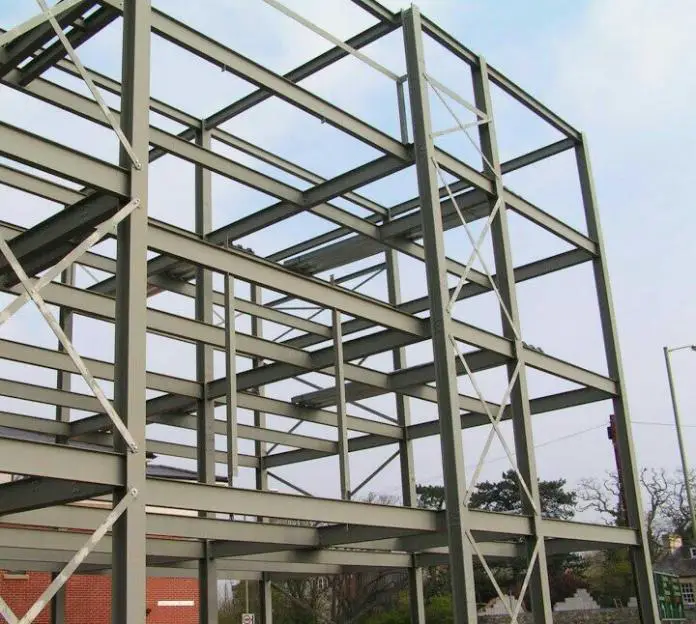
Universal beam sections are normally employed in buildings to carry floor and wall load. Loads on beams may include the load from slab, walls, building services, and their own self-weight. It is necessary for structural beams to satisfy ultimate and serviceability limit state requirements. This post gives a solved design example of a laterally restrained beam according to BS 5950.
The structural design of steel beams to BS 5950 involves following specific guidelines and principles outlined in the British Standard. BS 5950 is a widely used code of practice for the design of steel structures in the United Kingdom, but has been replaced by Eurocode 3 (EN 1993-1-1).
When designing steel beams, several factors are considered to ensure structural integrity and safety. These factors include determining the appropriate loadings, selecting the appropriate section shape and size, analyzing the beam’s resistance to bending, shear, and deflection, and ensuring proper connection details.
The code specifies various load combinations, such as dead loads, live loads, wind loads, and imposed loads, that need to be considered during the design process. In terms of section selection, the code provides tables and charts to determine the suitable steel section based on the applied loads and required span. These sections include universal beams (UB), universal columns (UC), and parallel flange channels (PFC), among others. The appropriate section is chosen based on its moment resistance, shear capacity, and deflection limits.
Design calculations involve checking the beam’s capacity to resist bending, shear, and deflection. These calculations consider the applied loads, section properties, and material properties of the steel. The code provides formulas and design charts to assess these aspects.
Steel Beam Design Example
A laterally restrained beam 9m long that is simply supported at both ends support a dead uniformly distributed load of 15 kN/m and an imposed load uniformly distributed load of 5 kN/m. It also carries a dead load of 20 kN at a distance of 2.5m from both ends. Provide a suitable UB to satisfy ultimate and serviceability limit state requirements (Py = 275 N/mm2).
Solution
At ultimate limit state;
Concentrated dead load = 1.4Gk = 1.4 × 20 = 28 kN
Uniformly distributed load = 1.4Gk + 1.6Qk = 1.4(15) + 1.6(5) = 29 kN/m
Support Reactions
Let ∑MB = 0; anticlockwise negative
(9 × Ay) – (29 × 9 × 4.5) – (28 × 6.5) – (28 × 2.5) = 0
Ay = 158.5 kN
Let ∑MA = 0; clockwise negative
(9 × By) – (29 × 9 × 4.5) – (28 × 6.5) – (28 × 2.5) = 0
By = 158.5 kN
Internal Stresses
Moment
MA = 0 (Hinged support)
MC = MD = (158.5 × 2.5) – (29 × 2.5 × 1.25) = 305.625 kNm
Mmidspan = (158.5 × 4.5) – (29 × 4.5 × 2.25) – (28 ×2) = 363.625 kNm
Shear
QA = Ay = 158.5 KN
QCL = 158.5 – (29 × 2.5) = 86 kN
QCR = 158.5 – (29 × 2.5) – 28 = 58 kN
QDL = 158.5 – (29 × 6.5) – 28 = -58 kN
QDR = 158.5 – (29 × 6.5) – 28 – 28 = – 86 kN
QB = 158.5 – (29 × 9) – 28 – 28 = – 158.5 kN
Internal Forces Diagram
Structural Design to BS 5950
Py = 275 N/mm2
Initial selection of section
Moment Capacity of section Mc = PyS ——- (1)
Where S is the plastic modulus of the section
Which implies that S = Mc/Py = (363.625 × 10⁶)/275 = 1320963.636 mm3 = 1320.963 cm3
With this we can go to the steel sections table and select a section that has a plastic modulus that is slightly higher than 1320.963 cm3
Try section UB 457 × 191 × 67 (S = 1470 cm3)
Properties of the section;
Ixx = 29400 cm4
Zxx = 1300 cm3
Mass per metre = 67.1 kg/m
D = 453.4mm
B = 189.9mm
t = 8.5mm
T = 12.7mm
r = 10.2mm
d = 407.6mm
Strength classification
Since T = 12.7mm < 16mm, Py = 275 N/mm2
Hence ε = √(275/Py) = √(275/275) = 1.0
Section classification
Flange
b/T = 7.48 < 9ε; Flange is plastic class 1
Web
d/t = 48 < 80ε; Web is also plastic class 1
Shear Capacity
As d/t = 48 < 70ε, shear buckling need not be considered (clause 4.4.4)
Shear Capacity Pv = 0.6PyAv —– (2)
Pv = 0.6PytD = 0.6 × 275 × 8.5 × 453.4 = 635893.5 N = 635.89 kN
But design shear force Fv = 158.5 kN
Since Fv(158.5) < Pv(635.89), section is ok for shear.
Now, 0.6Pv = 0.6 × 635.89 = 381.54 kN
Since Fv(158.5 kN) < 0.6Pv(381.54 kN), we have low shear load.
Moment Capacity
Design Moment = 363.625 kNm
Moment capacity of section UB 457 × 191 × 67 (S = 1470 cm3 = 1470 × 103 mm3)
Mc = PyS = 275 × 1470 × 103 = 404.25 × 10⁶ N.mm = 404.25 kNm
1.2PyZ = 1.2 × 275 × 1300 × 103 = 429 × 106 N.mm = 429.00 kNm
Mc (404.25 kNm) < 1.2PyZ (429.00 kNm) Hence section is ok
Evaluating extra moment due to self-weight of the beam
Self-weight of the beam Sw = 67.1 kg/m = 0.658 kN/m (UDL on the beam)
Moment due to self weight (Msw) = (ql2)/8 = (0.658 × 92)/8 = 6.66 kNm
(363.625 + 6.66) < Mc (404.25 kNm) < 1.2PyZ (429.00 kNm) Hence section is ok for moment resistance.
Deflection Check
We check deflection for the unfactored imposed load; E = 205 kN/mm2 = 205 × 106 KN/m2; Ixx = 29400 cm4 = 29400 × 10-8 m4
The maximum deflection for this structure occurs at the midspan and it is given by;
δ = (5ql4)/384EI = (5 × 5 × 94) / (384 × 205 × 106 × 29400 × 10-8) = 7.087 × 10⁻³ m = 7.087 mm
Permissible deflection; L/360 = 9000/360 = 25mm
7.087mm < 25mm. Hence deflection is satisfactory.
Web bearing
According to Clause 4.5.2 of BS 5950-1:2000, the bearing resistance Pbw is given by:
Pbw = (b1 + nk)tPyw —– (3)
Where;
b1 is the stiff bearing length
n = 5 (at the point of concentrated loads) except at the end of a member and n = 2 + 0.6be/k ≤ 5 at the end of the member
be is the distance to the end of the member from the end of the stiff bearing
k = (T + r) for rolled I- or H-sections
T is the thickness of the flange
t is the web thickness
Pyw is the design strength of the web
Web bearing at the supports
Let us assume that beam sits on 200 mm bearing, and be = 20mm
k = (T + r) = 12.7 + 10.2 = 22.9mm;
Hence n = 2 + 0.6(20/22.9) = 2.52mm < 5mm.
Pbw = (b1 + nk)tPyw
Pbw = [200 + 2.52(22.9)] × 8.5 × 275 = 602392.45 N = 602.392 kN
Pbw (602.392 kN) > Fv (158.5 kN) Hence it is ok
Contact stress at supports
Pcs = [b1 × 2(r +T )]Py = [200 × 2(22.9)] × 275 = 2519000N = 2519 kN
Pcs (2519 KN) > Fv (158.5 KN) Hence contact stress is ok
Web buckling
According to clause 4.5.3.1 of BS 5950, provided the distance αe from the concentrated load or reaction to the nearer end of the member is at least 0.7d, and if the flange through which the load or reaction is applied is effectively restrained against both;
(a) rotation relative to the web
(b) lateral movement relative to the other flange
The buckling resistance of an unstiffened web is given by;
Px = [25εt/√(b1 + nk)d] Pbw —– (4)
When αe < 0.7d, the buckling resistance of an unstiffened web is given by;
Px = [(αe + 0.7d)/1.4d] × [25εt/√(b1 + nk)d)] Pbw ————- (5)
Therefore, αe = 20mm + (200/2) = 120mm
0.7d = 0.7 × 407.6 = 285.32mm
αe(120mm) < 0.7d(285.32mm). Hence equation (5) applies;
Px = [(120 + 285.32)/(1.4 × 407.6)] × [(25 × 1 × 8.5 )/√((200 + 2.52 × 22.9) × 407.6)] × 602.392 = 280.538 kN
Px(280.538 kN) > Fv(158.5 kN) Hence it is ok.
Thank you for reading, and feel free to share.
Like Our Facebook page
www.facebook.com/structville


• It’s in reality a great and useful piece of information. I am happy that you simply shared this helpful info with us. Please keep us informed like this. Thank you for sharing.
CoBie adaptation in USA
Interference Analysis in USA
MEP F modelling in USA
Revit Modeling in USA
Fabrication Drawings preparation in USA
Shop Drawings Preparation in USA
Structural Analysis in USA
Point Cloud to BIM conversion in USA
ANIMATION SERVICES in USA
BIM Implementation in USA
Thank you Ubani Obinna Uzodimma for presenting such a clearly detailed design procedure
Simple and straight detailed example
Thank you so much
Am really appreciate for this easy way of learning.
Thank Engr for this solution.
But the check for lateral torsional buckling was not presented
Good stuff!
Lateral torsional buckling is a crucial check….
Stirling presentation!
Elaborate and simple!.. appreciated