8.7 C
New York
Saturday, October 19, 2024
Home Blog Page 54

Bonding of Old and New Concrete

In construction, there always comes a time when there is a need to bond hardened concrete (substrate) with fresh concrete topping/overlay. The aim of this post is to explain how to bond old and fresh concrete successfully. Furthermore, we will review the strength of the interfacial bond between old and new concrete based on laboratory studies.

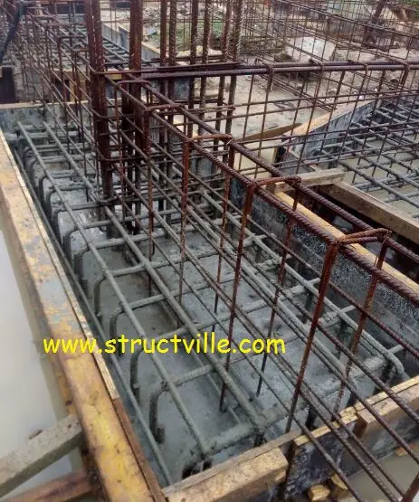
Proper bonding is very important for adequate performance when the fresh concrete topping is used to overlay an existing hardened concrete. This construction feature is usually found in bridge deck construction, concrete pavements, precast filigree slab, pile caps (in some cases) etc. Proper bonding between the substrate and the topping is not always guaranteed unless simple precautions are taken.

For adequate bonding, it is very important to prepare the surface of the substrate adequately. The preparation of the surface usually involves roughening the surface, and removal of all dirt, oil, grease, and loosened or unbonded portions of the existing concrete.

By implication, the surface of the substrate should be hard, firm, clean, and free from loosened particles. This can be achieved by the use of chipping hammers, wire brushing the surface etc. After this is done, the exposed concrete surface can be cleaned by using pressurised clean water, air, etc. The man hours involved depend on the area of the surface, location, and the ease of cleaning (e.g reinforcement obstruction).

precast%2Bfiligram%2Bslab


After surface preparation, there is usually a need to apply a bonding agent on the surface of the existing concrete in order to facilitate the bonding. Epoxy-based bonding agents are very popular for such operations. It is recommended that a bonding agent is applied prior to casting the fresh concrete.  In essence, the procedure should be ‘wet-to-wet’ as the bonding agent should not be allowed to dry before the fresh concrete topping is placed.

bonding%2Bagent
Hardened Concrete With Bonding Agent Ready for Topping/Overlay

In a research carried out by Vandhiyan and Kathiravan (2017), the compressive strength of monolithic and bonded concrete was compared using 150mm x 150mm cube specimens at 28 days. With an epoxy-based bonding agent, the compressive strength of the bonded concrete was about 5% less than the monolithic strength, while without the bonding agent, the compressive strength was about 28% less than the monolithic compressive strength.

Research has also shown that the moisture condition of the substrate affects the shear bond strength of bonded concrete. Shin and Wan (2010) investigated the interfacial bond strength of old and new concrete considering saturated surface dry (SSD) and air dry conditions. Saturated surface dry is a condition in which the concrete contains moisture that is equal to its potential absorption, without the surface being wet or damp.

At a water/cement ratio of 0.45 (for the topping concrete), the shear bond strength at the interface was about 44% greater when the substrate was at SSD condition than when it was air dry. At a water/cement ratio of 0.6 for the topping layer, an increase in shear bond strength was recorded, but there was a reduction in the compressive strength of the concrete.

So the recommendation in this article is that when casting a topping layer of fresh concrete on old concrete, adhere to the following guidelines;

(1) Prepare the surface properly
(2) Make sure that the substrate is at saturated surface dry condition
(3) Use a bonding agent and follow the manufacturer’s technical recommendation properly.

Thank you for visiting Structville today, and God bless you.

References
Vandhiyan R., Kathiravan M. (2017): Effect Of Bonding Chemical On Bond Strength Between Old And New Concrete. SSRG International Journal of Civil Engineering- (ICRTCETM-2017) – Special Issue – April 2017 ISSN : 2348 – 8352 pp 129-134

H-C. Shin,  Z. Wan (2010): Interfacial shear bond strength between old and new concrete. Fracture Mechanics of Concrete and Concrete Structures – Assessment, Durability, Monitoring and Retrofitting of Concrete Structures- B. H. Oh, et al. (eds) ⓒ 2010 Korea Concrete Institute, Seoul, ISBN 978-89-5708-181-5 pp 1195 – 1200

Meet the Winners of Structville Design Competition

In the month of May, we announced the commencement of Structville Design Competition, where civil engineering students and serving NYSC members from various universities and polytechnics in Nigeria competed for small tokens in the design of reinforced concrete structures. The exercise was aimed at developing the interest of students in Structural Design, and preparing them for excellence in the field of structural engineering. You can view the details of the competition below;


Structville Design Competition for Students

To view the result sheet of the competition, click the link below;

Structville Design Challenge Results

Let us meet the outstanding performers……

1st Position – USMAN UMAR (Ahmadu Bello University, Zaria)

IMG 20180216 221336

Usman Umar is a 500 level student from the Department of Civil Engineering, Faculty of Engineering, Ahmadu Bello University, Zaria, and he’s  an indigene of Ankpa LGA, Kogi State, Nigeria. While speaking to Structville during an interview, Usman dreams of becoming a structural engineer with vast experience in both consultancy and construction field, and he is quite willing to work with any consultancy or construction firm.

On what motivated him to study civil engineering, he said,

I grew up with the curiosity of learning the principles which guide the operations of machines and systems. By the time I was in secondary school I already knew I had to go for studying  an engineering course. Although I almost opted for electrical engineering while preparing for UTME, the awesomeness in the the construction of structures such as bridges and skyscrapers couldn’t let me. So I went for Civil Engineering.

Usman believes that a lot is being taught in Nigerian classrooms, but the technical know-how and the method of teaching adopted by a lecturer determine how much is impacted unto the students. Therefore, he believes that the Nigerian tertiary institutions are doing fairly good, but a lot more should be invested in order to raise the standard higher. 

Usman revealed that he has no definite studying pattern, but makes sure that he takes his courseworks seriously, and by consulting a lot of design textbooks and studying the architectural drawings carefully, he was able to do well in the Structville design competition.

So we all at Structville say a big congratulations to Usman Umar once again.

2nd Position – Ogungbire Adedolapo (Osun State University, Osogbo)


Adedolapo


Ogungbire Adedolapo Mojed, is a final year Civil Engineering student at Osun State University, Osogbo. He hails from Odo-Otin Local Government, Osun state. It has always been his childhood dream to grow up to become a Civil Engineer.

Adedolapo would like to own his own consultancy firm one day, and he believes that much experience will be needed in order to achieve that. He is aspiring to work with experienced Engineers and gain as much relevant experience as he can after graduating from the university. He is currently on the lookout for opportunities for pre-NYSC internship, and will be rounding off his degree programme by September 2018.

On the state of teaching and learning in Nigeria, he is an advocate of more practical approach to learning. According to him;

I believe a more practical approach will be more welcomed for training Civil Engineering students in the country. We should not only be bound to the theoretical examples that we have in textbooks but relate them to practical applications in Nigeria.

Adedolapo is curious to learn new things, and he flying high academically in his school. He said there was no special approach to the design competition on his own part. As an individual, he prefers self-studying and understanding the concepts behind what he is studying. That has helped him come a long way.

Congratulations Adedolapo once again.

3rd Position – Olajide Bukoye (Federal Polytechnic Offa, Kwara State)


IMG 20150531 171339 edit


Bukoye, Issa Abiola is a graduate of Federal Polytechnic, Offa in Kwara State. He is currently observing his mandatory National Service in Oyo state. Bukoye boasts of some years of field experience field experience and and have executed some practical designs in his career so far.

According to him,

Civil Engineering has always being my childhood dream not because it’s a lucrative job but because I want to make a difference. 70% of science students in high school wants to be a Doctor, but I’ve never for once dreamt of that because I’m good with numbers and I don’t want to waste the talent. I guess Civil Engineering has always been in my blood.

Bukoye believes that the quality of teaching in Nigeria is far from standard, but he is optimistic and hopeful of positive turnarounds. If he were to make changes in Nigeria, he would focus on the education system.

Bukoye is a goal driven person, and loves to take on any challenges because he believes that every challenge is an experience and once done and dusted, it goes to one’s achievements archive. After his NYSC program, he plans to secure a job and as well go back to school not just for the certificates but to learn more in the field of civil/structural engineering. 
 
We say a very big congratulations to you Bukoye.
 

Design of Ground Beams Using Staad Pro

Ground beams are employed in reinforced concrete substructures for a lot of reasons. They can be differentiated from plinth beams due to a slight variation in the purpose of their construction. Plinth beams are used to connect (chain) separate pad bases together, and blockwork can be built off the plinth beams. On the other hand, ground beams are designed mainly for the purpose of receiving load from the ground floor slab or raft, alongside other functions as envisaged by the designer.

In the design of beam and raft foundation, ground beams receive ground floor/raft slab pressure loads. These loads could be from earth pressure reactions or occupancy loads/dead loads.

Let us consider two cases as shown below:

Case 1: Raft Slab on Ground Beam Foundation

GROUND%2BBEAM
Fig 1: A typical section of a ground beam supporting a raft foundation

In this case, as shown in Fig 1, a raft foundation supported on ground beams is used to overcome the low bearing capacity of the soil. This is the cheapest alternative for constructing foundations on weak soils carrying relatively low/moderate superstructure load. The advantages of this method are;

(1) The volume of excavation to be done is reduced to a minimum since excavation will be done for the ground beams only
(2) It is relatively easy to construct
(3) The slab performs the triple function of acting as a structural raft slab, ground floor slab (oversite concrete), and damp proof course.

However, this construction method can demand beams that are slightly deeper than normal in order to raise the ground floor to a height above the compound level.

This type of foundation can be analysed and designed and using finite element analysis or rigid theory. When using the rigid theory, the arrangement of the foundation and the loadings have to be fairly symmetrical, and the footing will have to be stiff enough in order to assume full rigidity. Furthermore, we usually assume that the stiffness of the raft slab covers the weak patches of the soil adequately.

The implication of the rigid theory in design is that the settlement of the soil will even out under the rigid footing, with high internal forces developing in the slab. When a flexible approach is used, there would be a differential settlement, but lower stresses on the elements, thereby leading to a more economical design. Note that rigidity criteria are a function of superstructure stiffness and soil stiffness. Different codes of practice have their own definition of rigidity.

In the rigid method, usually, the soil pressure on the slab is evaluated, and transferred to the beams by assuming a sort of combined footing approach.

Case 2: Ground Floor Slab on Ground Beam 

2222
Fig 2: Ground beams on pile caps

In this approach as shown in Figure 2, the ground floor slabs are supported directly by ground beams, which in turn are supported by pile caps. In this case, the slabs are designed as suspended slabs, and ground pressure reactions are not taken into account.

Worked Example

Let us assume that you have a raft foundation on ground beams to design, and you have been able to obtain the soil pressure. Note that the variation of soil pressure is usually a function of location and the applied loading. See an example of how to determine it below;

Structural Design of Flat Raft Foundation (Rigid Approach)

Let us assume that in the example above, we will be introducing ground beams (1200mm x 225mm) along the column axes as shown in Figure 3. Let the thickness of the slab be 200 mm.

Design%2Bof%2Braft%2Bfoundation
Fig 3: Sketch of how ground beams were introduced in the model

From the analysis, the maximum pressure on the raft slab was discovered to be 49.975 kN/m2. Note that with the introduction of the ground beams, the 1000 mm projection is no longer necessary. So a simplified way of analysing and designing the ground beams using Staad Pro is as follows.

Step 1: Model the ground beam as appropriate and support it with pinned support at the column points. Also, assign the properties of the beam (1200 mm x 225 mm).

st%2Bmodel
Fig 4: Modelling of the ground beams on Staad Pro

Step 2: Create/add a ‘floor load’ and assign it to the beams as shown below. This uses the tributary area method to transfer the load to the beams;

FLOOR%2BLOAD
Fig 5: Application of ground pressure load

Remember that the load is assigned a positive value because it is an upward pressure.

Step 3: Run the analysis to obtain the bending moment given below.

Internal%2Bstresses%2Bdiagram

Let us consider the beam along grid line B.

BENDING%2BMOMENT%2BDIAGRAM%2BGROUND%2BBEAM
Bending Moment Diagram
SFD
Shear Force Diagram

The result from Staad Pro software indicates that the maximum span moment is 463 kNm. With this, you can provide the reinforcements at ULS depending on the code of practice you are using. Note that where applicable, you might need to consider wall loads, self-weight, etc, but note that these gravity forces will be likely beneficial because they will reduce the resultant load on the beam due to earth pressure. This is just a simple and straightforward approach that would always yield conservative results.

Thank you for visiting Structville today, and God bless you.


Different Methods of Staircase Modelling, Analysis, and Design

Staircases provide simple solutions for vertical circulation in a building. In this article, we will present the different methods of modelling a simple reinforced concrete staircase for the purpose of analysis and structural design.

The different methods considered in this article are as follows;

(1) Modelling the staircase using finite element plates
(2) Modelling the staircase as a simple 2D frame
(3) Modelling the staircase as a linear simply supported beam

The aim of this post is to compare the results obtained from the different modelling alternatives and give reinforced concrete designers a little idea about the results to expect from their assumptions.

Let us consider a section of a staircase with dimensions as shown below;

12345
Fig 2: Section of Staircase

The loading on the staircase is as follows;

Ultimate load on the flight = 15.719 kN/m2
Ultimate load on the landing = 14.370 kN/m2
Width of staircase = 1000 mm

We are going to model and analyse the staircase section shown using the three different methods described above.

Finite Element Plate Model (Staad Pro)

In this approach, the full dimensions and geometry of the staircase will be modelled using finite element plates. The thickness of the waist of the staircase will be assigned as the thickness of the plates, while the rise and threads will be ignored. The size of the finite element plates can be chosen to be square or rectangular but is preferable to keep the model uniform.

The 3D model of the staircase is given below;

rendered%2B3d
Fig 3: Rendered 3D Model of the Staircase

To consider the effect of the support condition on the behaviour of the staircase, it will be modelled as pinned-pinned condition and pinned-roller support condition.

Pinned-pinned supports

file%2Bview
Fig 4: Model of the staircase with pinned-pinned support

The static analysis of the structure gave the result below;

MX
Fig 5: Transverse Bending Moment on the Staircase (Mx)
MY
Fig 6: Longitudinal Bending Moment (My) on the Staircase

Pinned-roller support

pinned roller
Fig 7: Modelling the Staircase with Pinned-Roller Support

The analysis result gave the following;

Fig 8: Transverse Bending Moment (Mx)
rp%2Bmy
Fig 9: Longitudinal Bending Moment (My)

Static 2D Frame Model

In this case, the geometry of the staircase (height, landing, and angle of flight) is modelled as line elements and analysed as a 2D frame subjected to static load. The typical model is shown below.

Pinned-Pinned Support

2d

The result is as given below;

simple%2Bbeam
Fig 10: Bending moment on the Staircase (Frame Model; pinned-pinned support)

Pinned-Roller Support

pinned roller%2Bbeam
Fig 11: Bending Moment on the staircase (pinned-roller model)

Simply Supported Beam Model

In this case, the entire geometry of the staircase is idealised and analysed as a simply supported linear beam model as shown below.

manual
Figure 12: Bending Moment on the stair (simply supported beam model – horizontal length)

Discussion of Results

  1. The analysis results using the above-named methods gave all the bending moments in the staircase to be sagging.
  2. The finite element plate model gave the maximum sagging at the flight to be 41.1 kNm (see Fig 5), while the maximum sagging moment on the landing was found to be 32.6 kNm (see Fig 6). This result was found in both the pinned-pinned and pinned-roller model, therefore, there is no difference in using any of the support conditions in Staad Pro.
  3. The static 2D frame model of the staircase gave the maximum sagging moment on the flight to be 41.1 kNm, while the maximum sagging moment on the flight was 33.82 kNm (see Fig 10 and 11). In principle, it can be said there is no difference in modelling the staircase as a simple 2D frame or as a 3D plate model. The former is quicker and less complicated.
  4. The model of span dimension adopted for the manual equivalent beam calculation was picked from SCALE software, and the maximum moment on the flight was found to be 36.04 kNm (see Fig 12). This is about 12.3% less than other models. A little consideration will show that this effect stems from the span dimensions.

To take care of this, let us modify the flight dimensions as follows;
Lf,m = Lf/cos ϕ
Where Lf is the horizontal span of flight,  Lf,m is the actual length of the flight, and ϕ is the angle of inclination of the flight.

Thus; Lf,m = 1.75m/cos 34.4 = 2.12m

This gave the result below;

modified
Fig 13: Bending moment on the stair (simply supported beam model, developed length)

We can see that is more comparable and conservative when compared with results from computer models. Therefore, for all simple staircases, we can use the developed length of the flight instead of the horizontal length to analyse the staircase as a simply supported beam. However, when checking for deflection, we should use the horizontal length.

Thank you for visiting Structville today. God bless.


Deflection of Elastic Systems Using Castigliano’s Theorem

Castigliano’s method for calculating deflections is an application of his second theorem, which states that if the strain energy of a linearly elastic structure can be expressed as a function of generalised force Pi then the partial derivative of the strain energy with respect to generalised force gives the generalised displacement wi in the direction of Pi.

The second theorem of Castigliano is applicable to linearly elastic (Hookean material) structures with constant temperature and unyielding supports.

In general, this is given by;

wi = ∂U/∂Pi

The strain energy stored in a linear elastic system due to bending is given by;

strain%2Benergy

Solved Example
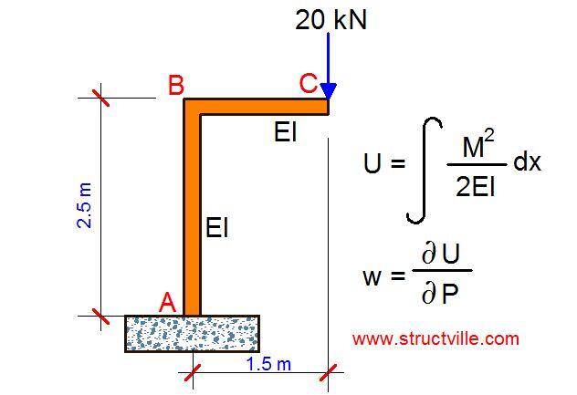
For the frame loaded as shown below, let us find the vertical deflection at point C due to bending using Castigliano’s theorem.

FRAME

Solution
Section BC
Mx = -20x

U1 = ∫[(-20x)2/2EI] dx  =  ∫ -400x2/2EI = -400x3/6EI
Knowing that the limit x = 1.5m;
U1 = 225/EI

Section AB
My = (-20 × 1.5m) = 30 kNm

U2 = ∫[(-30)2/2EI] dy  =  ∫ -900/2EI = -900y/2EI
Knowing that the limit y = 2.5m;
U2 = 1125/EI

Total strain energy = U1 + U2 = (225/EI) + (1125/EI) = 1350/EI

Let the vertical deflection at point C be δv

Work done by the externally applied load = 1/2(P × δ)
Work done = Strain energy stored in the system

1/2(20 × δ) = 1350/EI

δv = 135/EI metres

Structville Design Challenge Results (1st Edition)

result

On 14th of May, 2018, Structville Integrated Services announced the commencement of Structville Design Challenge for civil engineering students in Nigeria. (If you missed it, you can read post HERE). By the special grace of God, the competition has come and gone, and I wish to appreciate everyone who participated in the exercise.


The price money goes as follows;
1st position – NGN 10,000
2nd position – NGN 3,000
3rd position – NGN 2,000

Competition Details
Total number of successful applicants = 20
Total number of scripts submitted by dead line = 14
Total number of accepted scripts = 12
Total number of assessed scripts = 12

Rationale
Human capacity building in Nigeria has become a necessity, and we must all wake up to that fact. The motivation to start up something is one thing, but staying motivated to finish it up is another thing. The main aim of this competition was to steer the younger generation to a path of creativity, curiosity, technical capacity, problem solving, and tenacity. It was also designed to make them optimistic and look forward to a wonderful career in structural engineering.

While assessing the scripts, I made a lot of observations, and I will briefly summarise them using the points below;

GROUND%2BFLOOR%2BPLAN

FIRST%2BFLOOR%2BPLAN

(1) A lot of participants disregarded the first instruction of the exercise which was to pay attention to details. A lot of people lost marks by assuming weight of finishes, when the details of the finishes were clearly specified. Other people quoted values and formulars without properly referencing them. This affected a lot of people.

(2) In most cases, there was poor reading and interpretation of the architectural drawing. All those who modified the structure significantly lost a lot of marks.  However, I saw a lot of brilliance in some people with the way they managed the complexities of the architectural drawing, and produced a very good design. Some others came up with interesting GA’s that are stable and buildable, but not very economical, so they lost marks in that aspect. For some others, they came up with GA’s that are good, but did not reflect it properly in their analysis.

(3) No single person from South-East or South-South part of Nigeria participated in the exercise. I hope to see more of them next time.

(4) Finally, structural design is not about evaluating  M/fcubd2 and providing 2Y16, but it is more about the processes that led to the result, and the ability to execute the design economically, with adequate reliability.

So this is the result of the challenge;

RESULT%2BSHEET

I wish to say a very big congratulations to the winners;

1st PositionUSMAN UMAR (Ahmadu Bello University, Zaria)
2nd PositionOgungbire Adedolapo (Osun State University, Osogbo)
3rd PositionOlajide Bukoye (Federal Polytechnic Offa, Kwara State)

We will be celebrating them with their certificates and prize money in our next post. Structville will engage all the participants with corrections, recommendations, and discussion on all aspects of the design. Thank you, and God bless you.


Design of Precast Seating Decks for Stadium

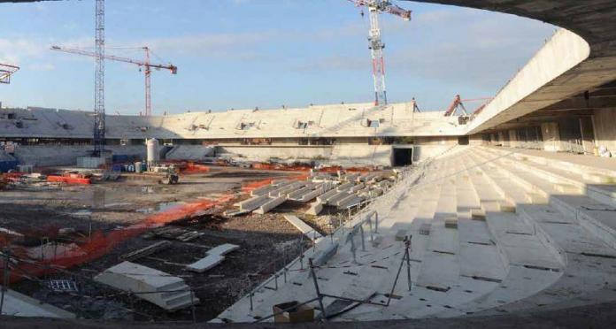
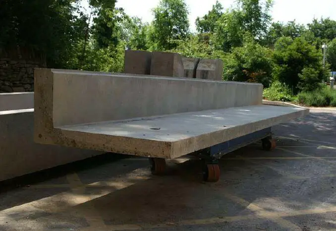
One of the most common concepts for the construction of sports stadiums today involves having precast concrete terrace units (seating decks) spanning between raker beams while at the same time, resting on each other. The successive arrangement of these precast seating units on the raker beams forms the grandstand of the stadium. The raker beams are usually formed in-situ with the columns of the structure and form part of the structural frame of the grandstand. It is also feasible to construct precast raker beams as was done in the Corinthians Arena Sao Paolo, Brazil for the 2014 FIFA world cup.

precasting%2Bseaating%2Bunits
Double L precast seating units for stadium


Grandstand%2BDesign
Typical section through a grandstand

Precast seating decks are usually made of L-shaped reinforced concrete units of length between 7-8 meters spanning between the raker beams. The seating decks also rest on each other. The role of the third (resting support) is to stop the units from undergoing excessive twisting, and in general, provide extra stability. 

Seating units are used to span between raker beams and form the exposed surface to which the seats are bolted onto. The seating units are fabricated in moulds depending on the length of the span, angle of inclination/curve, and support conditions. The precast seating units can be easily installed on-site, and when the joints between units have been sealed, they form an effective barrier against external elements. They can also be easily installed in steel structures.

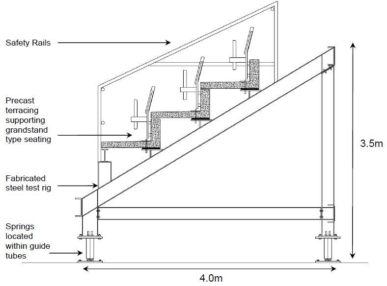
In a 2011 study at the University of Bath, human perception of vibration due to synchronised crowd loading was studied. Standard precast seating decks of 5.6 m length were used for the study. The precast seating decks used in the study were surpluses from a real premiership stadium project. The initial design length was 7.6 m but was cut to 5.6 m for the purpose of the study. The set up of the test rig is shown below.

browning stadium test rig model
Grandstand test set-up (Browning, 2011)

The precast seating deck used in the study was designed according to the requirements of BS 8110-1:1997 with a design live load of 4 kN/m2 for an assembly area with fixed seating. The live load was increased to 5 kN/m2 to allow for dynamic magnification (Browning, 2011). The model was observed to have an empty natural frequency of 6.47 Hz.

L shaped precast unit for stadium
Precast seating deck used in the study (Browning, 2011)

In a 2018 study in Romania, the serviceability of stadium seating decks under dynamic loading was evaluated. In the study, precast seating decks 150 mm thick with a total span of 9.28 m were used. The length of the horizontal flange was 990 mm while the vertical flange was 440 mm. Under the support conditions used in the study, a natural frequency of 6.75 Hz in the unloaded state was observed from the experiment. When numerically evaluated, a natural frequency of 6.76 Hz was observed for the unloaded structure and 4.75 Hz for the loaded structure.

The British design code BS 6399-1 sets the lower limit of the fundamental frequency for vertical vibrations of unloaded seating decks to 8.4 Hz, while the Green Guide (IStructE Dynamic performance for Permanent Grandstands subject to Crowd Action, 2008) set the same limit to 6 Hz but taking into account the weight of people on the structure. The authors concluded from the study that the section satisfied structural safety requirements, but human comfort due to vibration may be a major concern.

Design Example

Let us design a 6m long precast seating deck for a stadium with a section shown below;

section%2Bof%2Bterrace%2Bunit

fcu = 35 N/mm2; fyv = 460 N/mm2; fy = 460 N/mm2
Concrete cover = 30 mm
Unit weight of concrete = 24 kN/m3

Loading Analysis
Load type = uniformly distributed loading

Dead Load
Self weight of the unit = (24 × 0.15 × 0.25) + (24 × 0.15 × 0.95) = 4.32 kN/m
Make allowance for stair units, seats, and railings = 2 kN/m2

Live Load
For grandstands with fixed seating = 4 kN/m2
Making allowance for dynamic magnification qk = 5 kN/m2

At ultimate limit state;
n = 1.4gk + 1.6qk
n = 1.4(6.32) + 1.6(5) = 16.848 kN/m

loading

Design Moment Mmax @ 3.0m = (ql2)/8 = (16.848 × 62)/8 = 75.816 kN.m
End shears V = ql/2 = (16.848 × 6)/2= 50.544 kN

Design of the section (web) to resist the applied moment
M = 75.816 kN.m
Effective depth d = h – Cc – ∅⁄2 – ∅links

Assuming Y16mm for main bars and Y8mm for links
d = 400 – 30 – 10 – 8 = 352 mm

b = bw = 150mm (since the flange is at the tension zone)
k = M/fcubd2 = (75.816 × 10⁶)/(35 × 150 × 3522) = 0.116
la = 0.5 + √[0.25- 0.116/0.9] = 0.848

ASreq = M/(0.95fy.la.d) = (75.816 × 10⁶)/(0.95 × 460 × 0.848 × 352) = 581.22 mm2

In the web, provide 2Y16mm + 2Y12mm (ASprov = 628 mm2)
Provide 2Y12mm (Asprov = 226 mm2) in the compression zone (as hanger bars)

Spread the As,req also along the width of the tread
Provide Y12 @ 175mm c/c Top and Bottom (Asprov = 646 mm2/m)

Distribution bars
Provide Y10 @ 200mm c/c as closed links

Deflection Check
Basic span/effective depth ratio = 20 (for simply supported beams)

Modification factor for tension reinforcement
Service stress fs = (2fyAsreq)/(3Asprov) = (2 × 460 × 581)/(3 × 628)
fs = 283.715 N/mm2
m.f = 0.55 + (477 – fs) / 120(0.9 + M/bd2)
m.f = 0.55 + (477 – 283.715) / 120(0.9 + 4.079) = 0.873

Modification factor for compression reinforcement
1 + (100A’sprov/bd)/(3 + 100A’sprov/bd) = 1.124

Limiting span/effective depth = 0.873 × 1.124 × 20 = 19.625
Actual span/effective depth = 6000/352 = 17.045
Actual < Limiting, therefore deflection is okay

Design of the section to resist shear
Critical end shear V = 50.544 kN
Shear stress v = V/bd = (50.544 × 10³) / (150 × 352) = 0.957 N/mm2

0.957 N/mm2 < 0.8 √35 < 5 N/mm2

Concrete resistance shear stress
vc = 0.632 × (100As/bd)1/3 × (400/d)1/4
vc =0.632 × [(100 × 628)/(150 × 352)]1/3 × (400/352)1/4
vc = 0.632 × 1.059 × 1.032 = 0.69 N/mm2

For concrete grades greater than 25 N/mm2
vc = vc(fcu/25)1/3 = 0.69 × (35/25)1/3 = 0.772 N/mm2

0.772 N/mm2 < 0.957 N/mm2
0.5 vc < v < (vc + 0.4)

provide minimum links with spacing
sv = (0.95AsvFyv)/0.4bv
(Trying 2 legs of Y8mm bar)
sv = (0.9 5 × 107 × 460)/(0.4 × 150) = 735.62mm

Maximum spacing of links = 0.75d
0.75 × 352 = 264m
Provide Y8 @ 250mm c/c links

Simplified dynamic consideration of the section
BS 6399 part 1: 1996 gave the following limit for the vertical frequency for structures subject to synchronized crowd loads = 8.4 Hz. IStructE Dynamic Performance for permanent Grand Stands (2008) gave the following limits;

3.5 Hz for viewing typical sporting events and classical concerts.
6 Hz for pop concerts and high-profile sporting events.
(3.5 Hƶ is given as the minimum vertical frequency acceptable for an empty grandstand).

The natural frequency for simply supported beams subjected to UDL (when the grandstand is empty, consider dead load only) is given by (considering the first mode of vibration);

fn = π/2[gEdIt/(wL4)]0.5 (See Salyards and Hanagan, 2005)

Where;
Ed = dynamic modulus of elasticity of the concrete.
It = Transformed moment of inertia
L = Span of section
g = acceleration due to gravity (m/s2)
w = Applied load (udl) = gk = 6.32 kN/m

An empirical relationship for concrete’s elastic modulus and dynamic modulus is given below;

Ec = 1.25Ed – 19 (BS 8110-2)

Where both units of Ec and Ed are in kN/mm2

Ec,28 = 20 + 0.2fcu = 20 + 0.2(35) = 27 kN/mm2

This expression does not apply for lightweight concretes or concrete that contains more than 500 kg/m3 of cement.
Hence, Ec = 1.25Ed – 19
27 kN/mm2 = 1.25Ed – 19
Ed = 46/1.25 = 36.8 kN/mm2

Ed = 3.68 x 10⁷ kN/m2
EdIt = 3.68 x 107 x 1.65 x 10–3 = 60720 kN/m2
To account for a cracked section, let us say EdIt = 0.75 x 60720 = 45540 kN/m2

Therefore the natural frequency;
fn = π⁄2 [(9.81 × 45540)/(6.32 × 64)]0.5 = 11.6 Hz

This satisfies the IStructE and BS 6399 requirements for empty grandstands. The natural frequency should also be calculated for the whole structure (3D frame) and compared with the natural frequency of the precast units. However, Salyards and Hanagan (2005) recommended that when the natural frequency of the individual seating units is way higher than the expected natural frequency of the entire structure, they could be neglected in the 3D modelling.

Detailing Sketches

section%2Bdetailing


Concealing of PVC pipes in RC Columns

In modern building construction, PVC pipes (plumbing works) on the surface of buildings is not always very desirable. In a country like Nigeria, PVC surface pipes deteriorate quickly due to weather conditions thereby leading to increased maintenance costs. On the other hand, they are usually not aesthetically pleasing.

surface%2Bpiping
Fig 2: Surface piping in a building


To solve this problem, architects normally provide ducts for MEP services (which is the best practice) during the design of a building. Another option that is normally considered is to conceal the pipes in walls or structural members.

Two things are actually involved;

(1) If it is an intentional design, or
(2) if it is an afterthought.

When it is part of the design, the structural engineer takes into account the effect of the pipes before producing working drawings. But when it is an afterthought, there is need to carry out checks and evaluate the effect of the plumbing work on the structural element before signing off.

pipe%2Bin%2Bwall
Fig 3: PVC pipe concealed in masonry wall

We have always seen situations in buildings where structural members are compromised in order to allow pipes and other services pass through. This should not be so because starting from the onset, we should realise that services are part of a building, and should be considered during the planning and design stage. The flow of services in a building should not be an afterthought.

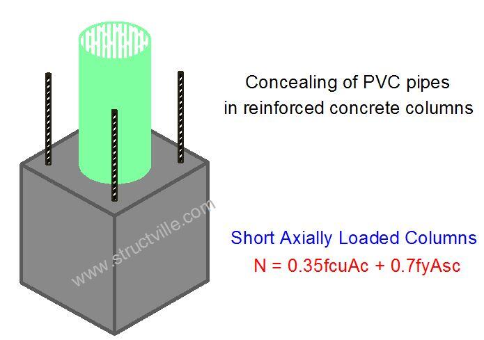
Let us use this example below to highlight the effect of installing PVC pipes in reinforced concrete columns.

Example
What is the effect of passing a 75 mm diameter pipe longitudinally through an axially loaded short reinforced concrete column with the following data?

Size of column = 230 x 230 mm
Grade of concrete = 25 Mpa
Grade  of steel = 410 Mpa
Reinforcement provided = 4Y16
Design axial load on column = 593 kN


Solution

From equation (39) of BS 8110-1:1997;

N = 0.35fcuAc + 0.7fyAsc

From the data provided above;
Asc = 804 mm2 (4Y16)
A=  (230 x 230) – 804 = 52096 mm2
N = [(0.35 × 25 × 52096) + (0.7 × 410 × 804)] = 686588 N = 686.588 kN

686.588 kN > 593 kN (Therefore column is adequate without the pipe)

On introducing the 75mm PVC pipe;
Area of pipe = (π × d2)/4 = (π × 752)/4 = 4417.86 mm2

Hence;
A=  (230 × 230) – 804 – 4417.86 = 47678.14 mm2
N = [(0.35 × 25 × 47678.14) + (0.7 × 410 × 804)] = 647931.725 N = 647.931 kN
647.931 kN > 593 kN (Therefore column is still adequate with the 75 mm pipe passing through it)

However, we should anticipate more complex interaction and verifications when the loading of the column is complex. Apart from the reduction in load carrying capacity of columns, care should be taken to ensure that the concrete is well consolidated to avoid honeycombs especially around the pipes. Also adequate care should be taken to ensure that the pipes are not leaking (inclusive of the joints) by pressure testing before concreting is done. Leakage of pipes might compromise the reinforcements by corrosion.

Summarily, adequate design and planning for pipe network in a building is the best solution – all options available should be evaluated. As far as possible, it is best to let the structural members be.

Question of the Day (25/06/2018)

Structville daily questions
From now henceforth, Structville will be publishing daily questions on different aspects of civil engineering. You are expected to enter your response in the comment section. At the end of every week, exceptional participants will stand a chance to win some gifts. This exercise is open to participants all over the world.

Today’s Question
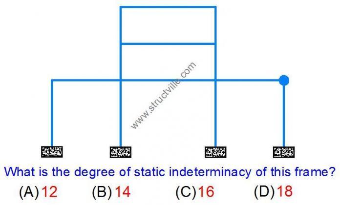
What is the degree of static indeterminacy of the frame shown above?

Thank you for participating in exercise today, remember to enter your answer in the comment section. The main aim of this exercise to stimulate knowledge of structural analysis on the internet in a fun and exciting way. We are always happy to hear from you, so kindly let us know how you feel about Structville.

E-mail: info@structville.com
WhatsApp: +2347053638996

You can also visit Structville Research for downloads of civil engineering materials.

STRUCTVILLE REINFORCED CONCRETE DESIGN MANUAL
We have this very affordable design manual available…

final%2Bfront%2Bcover

Do you want to preview the book, click PREVIEW
To download full textbook, click HERE

Basic Information on Fire Protection of Buildings

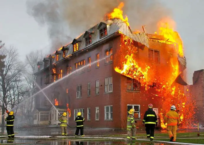
Fire outbreak is a problem in buildings since it causes loss of human lives, injuries, destruction of properties, and poses serious environmental challenges. Injury and loss of life are caused by heat, inhalation of toxic gases generated by combustion of furnishings/properties, falling debris, etc. Destruction of property and structural damage and failure are caused by heat and burning of combustible material.


Prevention and control of damage due to fire can be achieved through the following means;

(1) Early detection by smoke and heat detectors or manual sighting followed by extinction of the fire by automatic sprinklers, manual application of water, foams, fire extinguishers etc.

Fire%2Bsprinkler%2Bsystem
Fig 2: Fire Sprinkler System

(2) Containment of the fire by dividing the building into fireproof compartments to prevent fire spread and smoke travels, and provision of fireproof escape routes, fire rated doors and windows, fire rated finishes, etc.

Fire%2Brated%2Bdoors
Fig 3: Fire rated doors

(3) Fire protection of load bearing structural members to ensure collapse does not occur before people can escape or the fire be extinguished. This is usually achieved by giving the building a fire rating during the design process.

structural steel beam column spray 2
Fig 4: Beams and Columns Protected By Spraying

The last two control methods form an essential part of the design considerations for steel structures (architectural and structural). All multi-storey commercial and residential buildings require fire protection of structural members, but single-storey and some other industrial buildings might not need protection.


Fire resistance requirements of buildings are usually based on the parameters influencing fire growth and development. These include:

  • Fire [probability of Fire occurrence, Fire spread, Fire duration, Fire load, Severity of fire…]
  • Ventilation conditions
  • Fire compartment (type, size, geometry)
  • Type of the structural element
  • Evacuation conditions
  • Safety of the rescue teams
  • Risk for the neighbouring buildings
  • Active fire fighting measures

Structural Considerations in Fire Design
Structural steelworks lose their strength on exposure to fire. Temperatures commonly reach 1200°C at the seat of the fire, while the critical temperature for steel is about 550°C. (see brief calculation below). At this temperature the yield stress of steel has fallen to about 0.7 of its value at ambient temperatures that is to the stress level in steel at working loads.

calculation

For instance in the calculation above, the critical temperature (failure temperature) is found to be 603°C (calculation according to EC3). The next step in the calculation is to determine the time at which the bare section reaches the critical temperature. This can offer the right information about the type of protection needed.

To request for a fully solved example of fire design (PDF) in a building, contact the author by clicking HERE.

Types of Fire Protection for Steel Structures

  • Solid protection for columns, where the concrete assists in carrying the load (this is not so much used in modern construction). Beams can also be cased in concrete. A concrete thickness of 50 mm will give about 2 hours protection.
  • Brick-clad steel-framed buildings, where brick provides the walling and fire protection, are a popular building system.
  • Hollow casing can be applied in the form of pre-fabricated casing units or vermiculite gypsum plaster placed on metal lathing.
  • Profile casing, where vermiculite cement is sprayed on to the surface of the steel member, is the best system to use for large plate and lattice girders and is the cheapest protection method. A thickness of 38 mm of cement lime plaster will give about 2 hours protection.
  • Intumescent coatings inflate into foam under the action of heat to form the protective layer.
  • Fire resistant ceilings are used to protect floor steel.
Thank you for visiting Structville today, and God bless you.