A combined footing is a type of shallow foundation where a common base is provided for two closely spaced columns. When a common base in form of a strip is provided for three or more rows of columns, it is better described as a continuous footing. Combined footings are normally employed in cases where two or more columns are closely spaced such that their individual pad footings would overlap each other. They can also be used where property boundaries would not permit the design of separate bases.
The design of a combined footing involves the geotechnical and structural design, where the proper proportioning of the dimensions, thickness of the base, and proper reinforcement is provided. The foundation of a combined footing must not undergo excessive settlement or shear failure, and the footing itself must be strong enough to resist the bending moment and shear forces as a result of the superstructure load. The thickness of combined footings is usually governed by shear force considerations.
In the design of combined footings, the centre of gravity of the two column loads should as practically as possible coincide with the centre of area of the base. The base should preferably be rectangular in plan and symmetrically disposed about the line of loads. If it is not practicable to proportion the base as described above, the load will be eccentric, and the centre of pressure of the higher ground pressure will have the same eccentricity relative to the centre of the base.
If the base is thick enough, the pressure distribution diagram will be trapezoidal for eccentric loads, but uniform for concentric loads. If the base is relatively thin, the pressure distribution will be variable, with the maximum pressure occurring directly under each column.
The most common method of design of combined footings is the rigid approach, which makes the following assumptions.
- The footing is infinitely rigid, and therefore, the deflection of the footing does not influence the pressure distribution.
- The soil pressure is distributed in a straight line or a plane surface such that the centroid of the soil pressure coincides with the line of action of the resultant force of all the loads acting on the foundation.
However, flexible method can also be used for the design of combined footings, taking into account soil-structure interaction.
Solved example on the design of combined footing
Two (300 x 300)mm square columns spaced at a distance of 2.45 m c/c are loaded as shown below. The foundation is founded on soil of a bearing capacity of 125 kN/m2. It is desired to design the footing to satisfy all requirements using the concrete grade of 30 N/mm2 and steel of yield strength 500 N/mm2. The concrete cover is 50mm.
At serviceability limit state;
PEd = 1.0Gk + 1.0Qk
Total service load on column P1 = 665 + 122 = 787 kN
Total service load on column P2 = 825 + 145 = 970 kN
Total load on both columns = 787 + 970 = 1757 kN
Assuming 10% of the service load to account for the self-weight of the footing;
Sw = 0.1 × 1757 = 175.7 kN
Area of footing required = Total service load/Allowable bearing capacity = (1757 + 175.7)/125 = 15.46 m2
Adopt a rectangular base = 6.5m x 2.5m (Area provided = 16.25 m2)
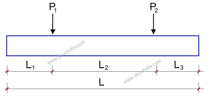
To locate the centroid of the footing, let us take moment about column P1;
(970 × 2.45) – 1757x = 0
On solving, x = 1.352m from column P1
Let the projection of the footing from the lighter column be L1
Therefore;
L1 + 1.352m = (Total length of footing)/2 = 6.5/2 = 3.25 m
Therefore, L1 = 3.25 – 1.352 = 1.898 m (say 1.9 m)
Hence L3 = 6.5 – (1.9 + 2.45) = 2.15 m
Alternatively, the footing can be proportioned using a straight-forward formula based on the calculations done above;
L3 = 0.5L – P1L2/(P1 + P2) = (6.5/2) – (787 × 2.45)/(787 + 970) = 2.15 m
The final disposition of the footing is given below assuming a trial footing depth of 600 mm.
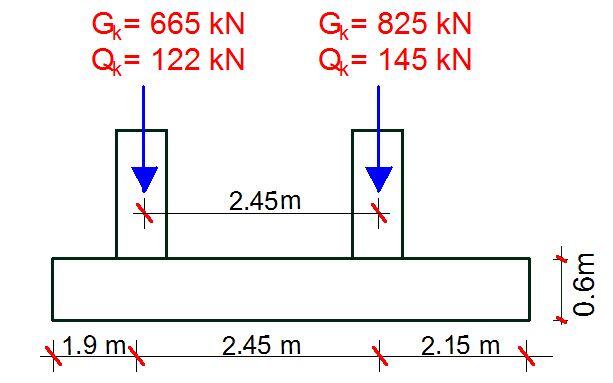
We can check the preliminary thickness of 600 mm by considering the punching shear at the column perimeter. At the column perimeter, the maximum punching shear stress should not be exceeded.
At ultimate limit state;
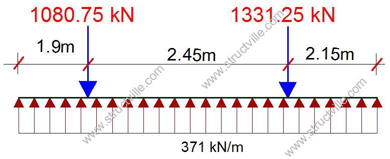
P1 = 1.35Gk + 1.5Qk = 1.35(665) + 1.5(122) = 1080.75 kN
P2 = 1.35Gk + 1.5Qk = 1.35(825) + 1.5(145) = 1331.25 kN
Total ultimate load = 1080.75 + 1331.25 = 2412 kN
VEd < VRd,max
Where;
VEd = βVEd /u0d
VRd,max = 0.5vfcd
Considering Column P2 bearing the maximum axial load, VEd = 1331.25 kN
β = 1.5 (an approximate value from clause 6.4.3(6) of EN 1992-1-1:2004)
u0 = column perimeter = 2(300) + 2(300) = 1200 mm
v = 0.6[1 – fck/250] (strength reduction factor for concrete cracked in shear)
v = 0.6[1 – 30/250] = 0.528
fcd = αccfck/γcfcd = (1.0 × 30)/1.5 = 20 N/mm2
VRd,max = 0.5 × 0.528 × 20 = 5.28 N/mm2
VEd = (1.5 × 1331.25 × 1000) / (1200mm × d)
Therefore;
1996874/1200d = 5.28
On solving;
The minimum thickness of footing dmin = 315.263 mm
Hence the depth provided exceeds the minimum required.
Earth pressure intensity at ultimate limit state = (1080.75 + 1331.25)/16.25 = 148.43 kN/m2
For a width of 2.5m, q = 148.43 × 2.5 = 371.075 kN/m
Bending moment at column P1 = (371 × 1.92)/2 = 669.65 kNm
Bending moment at column P2 = (371 × 2.152)/2 = 857.47 kNm
The maximum bending moment in the span will occur at the point of zero shear;
Mx = 371x2/2 – 1080.75(x – 1.9) = 185.5x2 – 1080.75x + 2055.425
∂Mx/∂x = 371x – 1080.75 = 0
On solving; x = 1080.75/371 = 2.91 m
Mmax = 185.5(2.91)2 – (1080.75 × 2.91) + 2055.425 = 479.275 kNm
The shear force just to the left of column P1 = (371 × 1.9) = 704.9 kN
The shear force just to the right of column P1 = 704.9 – 1080.75 = -375.85 kN
The shear force just to the left of column P2 = -375.85 + (371 × 2.45) = 533.1 kN
The shear force just to the right of column P2 = 533.1 – 1331.25 = -798.15 kN
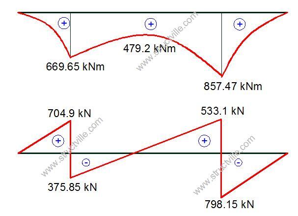
As an be seen, there is no hogging moment in the combined footing.
Bottom Reinforcement
We are supposed to take our maximum moment from the column face which can be easily determined as shown below.
MEd = 857.47 kNm
Effective depth (d) = 600 – 50 – 10 = 540 mm (assuming 20mm bars).
b = 2000mm
k = MEd/(fckbd2 )
k = (857.47 × 10⁶)/(30 × 2500 × 5402 ) = 0.039
Since k < 0.167 No compression reinforcement required
z = d[0.5 + √(0.25 – 0.882k)] = z = d[0.5 + √(0.25 – (0.882 × 0.039)] = 0.95d
As1 = MEd/(0.87fyk z)
As1 = (857.47 × 10⁶)/(0.87 × 500 × 0.95 × 540) = 3842 mm2
Provide 13H20mm @ 200mm c/c BOT (ASprov = 4082 mm2)
Top reinforcement
There is no hogging moment on the footing as shown in the bending moment diagram. However, we can provide minimum reinforcement at the top.
Asmin = 0.0013bd = (0.0013 × 1000 × 540) = 702 mm2
Provide H12mm @ 150mm c/c BOT (ASprov = 753 mm2/m)
Transverse Reinforcement
Cantilever arm = (2.5 – 0.3)/2 = 1.1 m
Designing per unit strip (per 1000 mm)
MEd = [148.43 × 1.12]/2 = 89.8 kNm
Effective depth (d) = 600 – 50 – 10 = 540 mm (assuming H20mm bars).
k = MEd/(fckbd2 )
k = (89.8 × 10⁶)/(30 × 1000 × 5402 ) = 0.010
Since k < 0.167 No compression reinforcement required
z = d[0.5+ √(0.25 – 0.882k)] = z = d[0.5+ √(0.25 – (0.882 × 0.010)] = 0.95d
As1 = MEd/(0.87fyk z)
As1 = (89.8 × 10⁶)/(0.87 × 500 × 0.95 × 540) = 402 mm2
Provide H12mm @ 200mm c/c BOT (ASprov = 565 mm2/m)
Check for shear
Clause 6.4.2(2) of EN 1992-1-1:2004 states that control perimeters at a distance less than 2d should be considered where the concentrated force is opposed by a high pressure (e.g. soil pressure on a base), or by the effects of a load or reaction within a distance 2d of the periphery of the area of application of the force.
Beam shear
Check critical section d away from the most loaded column face
VEd = 148.43 x (2 – 0.54) x 2.5 = 541.7 kN
vEd = (541.7 x 10³)/(2500 x 540) = 0.401 N/mm2
vRd, c = CRd, c × k × (100 × ρ1 × fck) 0.3333
CRd, c = 0.12
k = 1 + √ (200/d) = 1 + √ (200/540) = 1.608
ρ = 4082/(540 × 2500) = 0.00302
vRd, c = 0.12 × 1.608 × (100 × 0.00302 × 30)0.333 = 0.402 N/mm2
=> vEd (0.401 N/mm2) < vRd,c (0.402 N/mm2) Beam shear ok
Punching Shear
Punching shear: Basic control perimeter at 2d from face of column
vEd = βVEd/uid < vRd,c
β = 1,
ui = (300 x 4 + 540 x 2 x 2 x π) = 7986 mm
VEd = load minus net upward force within the area of the control perimeter)
VEd = 1331.25 – 148.43 x (0.302 + π x 1.0802 + 1.080 x 0.30 x 4) = 581.6 kN
vEd = (581.6 x 10³)/(7986 x 540) = 0.1348 N/mm2
Punching shear resistance of the section
VRd,c = [CRd,c.k.(100ρ1 fck)(1/3) ] × 2d/a ≥ (Vmin × 2d/a)
a = 540 + 540 = 1080 mm
CRd,c = 0.18/γc = 0.18/1.5 = 0.12
k = 1 + √(200/d) = 1 + √(200/540) = 1.606 > 2.0, therefore, k = 1.608
Vmin = 0.035k(3/2) fck0.5
Vmin = 0.035 × (1.608)1.5 × 300.5 = 0.391 N/mm2
ρx (in the transverse direction) = As/bd = 565/(1000 × 524) = 0.001078
ρz (in the longitudinal direction) = As/bd = 4082/(2500 × 540) = 0.003023
ρ1 = √(ρx × ρz) = 0.0018054 < 0.02
VRd,c = [0.12 × 1.608 (100 × 0.0018054 × 30 )(1/3)] × (2 × 540)/1080 = 0.338 N/mm2 (Take Vmin = 0.391 N/mm2)
0.1348 N/mm2 < 0.391 N/mm2
The section is ok for punching shear.
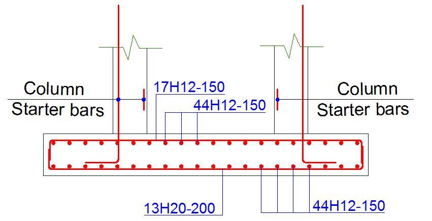
With this, the reinforcement detailing can be drawn.
Thank you for visiting Structville today.
Have you read…
How to Estimate The Cost of Tiling a Three Bedrooms Flat
Our facebook page is at www.facebook.com/structville





As per EN-7,Design of Foundations shall be performed in one of the 3 Design approaches, Direct Design case.Which Design approach to follow depends on the country of the project.
each approaches seriously affect the size and reinforcement detail. So, for a complete analysis and design of foundations as per Eurocode, applying one or all of the design approaches may seem reasonable.
Thanks
b=2500mm
you erroneously stated that b=2000mm
Though in your computation you’ve used the correct figure of 2500mm
Nonetheless,thanks for a very elaborate and simple approach.👍👍🏼