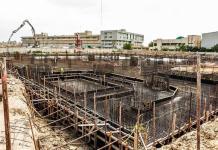
Ground beams are employed in reinforced concrete substructures for a lot of reasons. They can be differentiated from plinth beams due to a slight variation in the purpose of their construction. Plinth beams are used to connect (chain) separate pad bases together, and blockwork can be built off the plinth beams. On the other hand, ground beams are designed mainly for the purpose of receiving load from the ground floor slab or raft, alongside other functions as envisaged by the designer.
In the design of beam and raft foundation, ground beams receive ground floor/raft slab pressure loads. These loads could be from earth pressure reactions or occupancy loads/dead loads.
Let us consider two cases as shown below:
Case 1: Raft Slab on Ground Beam Foundation
In this case, as shown in Fig 1, a raft foundation supported on ground beams is used to overcome the low bearing capacity of the soil. This is the cheapest alternative for constructing foundations on weak soils carrying relatively low/moderate superstructure load. The advantages of this method are;
(1) The volume of excavation to be done is reduced to a minimum since excavation will be done for the ground beams only
(2) It is relatively easy to construct
(3) The slab performs the triple function of acting as a structural raft slab, ground floor slab (oversite concrete), and damp proof course.
However, this construction method can demand beams that are slightly deeper than normal in order to raise the ground floor to a height above the compound level.
This type of foundation can be analysed and designed and using finite element analysis or rigid theory. When using the rigid theory, the arrangement of the foundation and the loadings have to be fairly symmetrical, and the footing will have to be stiff enough in order to assume full rigidity. Furthermore, we usually assume that the stiffness of the raft slab covers the weak patches of the soil adequately.
The implication of the rigid theory in design is that the settlement of the soil will even out under the rigid footing, with high internal forces developing in the slab. When a flexible approach is used, there would be a differential settlement, but lower stresses on the elements, thereby leading to a more economical design. Note that rigidity criteria are a function of superstructure stiffness and soil stiffness. Different codes of practice have their own definition of rigidity.
In the rigid method, usually, the soil pressure on the slab is evaluated, and transferred to the beams by assuming a sort of combined footing approach.
Case 2: Ground Floor Slab on Ground Beam
In this approach as shown in Figure 2, the ground floor slabs are supported directly by ground beams, which in turn are supported by pile caps. In this case, the slabs are designed as suspended slabs, and ground pressure reactions are not taken into account.
Worked Example
Let us assume that you have a raft foundation on ground beams to design, and you have been able to obtain the soil pressure. Note that the variation of soil pressure is usually a function of location and the applied loading. See an example of how to determine it below;
Structural Design of Flat Raft Foundation (Rigid Approach)
Let us assume that in the example above, we will be introducing ground beams (1200mm x 225mm) along the column axes as shown in Figure 3. Let the thickness of the slab be 200 mm.
From the analysis, the maximum pressure on the raft slab was discovered to be 49.975 kN/m2. Note that with the introduction of the ground beams, the 1000 mm projection is no longer necessary. So a simplified way of analysing and designing the ground beams using Staad Pro is as follows.
Step 1: Model the ground beam as appropriate and support it with pinned support at the column points. Also, assign the properties of the beam (1200 mm x 225 mm).
Step 2: Create/add a ‘floor load’ and assign it to the beams as shown below. This uses the tributary area method to transfer the load to the beams;
Remember that the load is assigned a positive value because it is an upward pressure.
Step 3: Run the analysis to obtain the bending moment given below.
Let us consider the beam along grid line B.
| Bending Moment Diagram |
| Shear Force Diagram |
The result from Staad Pro software indicates that the maximum span moment is 463 kNm. With this, you can provide the reinforcements at ULS depending on the code of practice you are using. Note that where applicable, you might need to consider wall loads, self-weight, etc, but note that these gravity forces will be likely beneficial because they will reduce the resultant load on the beam due to earth pressure. This is just a simple and straightforward approach that would always yield conservative results.
Thank you for visiting Structville today, and God bless you.


Thanks for this publication.this is educative.
As started above, if the ground beam us assigned 1200mmx225mm, how deeply should this beam be below the natural ground level?
It depends on the site, and such things are supposed to be on the construction drawing. Consideration of flooding, groundwater level, etc will determine the height above natural ground level, while geotechnical parameters will likely influence depth below ground level.
am having problems adding the load… it does not work
• Congratulations for this wonderful blog. I found it very informative and interesting too. I have bookmarked your blog and will return in the future. I want to encourage you to continue that marvelous work, have a great daytime!
CoBie adaptation in USA
Interference Analysis in USA
MEP F modelling in USA
Revit Modeling in USA
As you're able view, by employing pool area underlay in addition to cove you will be secured an established setting up without the need of creases or maybe skin problems. Ones liner is utterly covered by almost any dangerous materials from the surface. see post
The analysis of 49kN/m2 is from staad.pro or from the soil bearing?
It was obtained from a previous analysis carried out. See the link below
https://structville.com/2018/01/structural-design-of-flat-raft-foundation-rigid-approach.html
Very educative and informative