Bridges are structures designed to span over obstacles, and as such provide access routes for humans, animals, vehicles, fluid, and other objects as may be desired. EN 1990 (Basis of Structural Design) classified bridges under consequence class 3 (CC3) which implies that the consequences are high if failure should occur. As a result, the design of bridges is taken very seriously and all possible load regimes that the structure will be subjected to in its design life are taken into account.
Bridges are important for adequate development, safety, and efficiency of road transportation system in any country including Nigeria. Nigerian engineers have stepped up to solve the engineering problems facing them internally and independently.
Loads from vehicles are one of the the most prominent loads that bridges are subjected to in their design life. Eurocode 1 Part 2 (EN 1991-2) handles the actions of traffic on bridges.
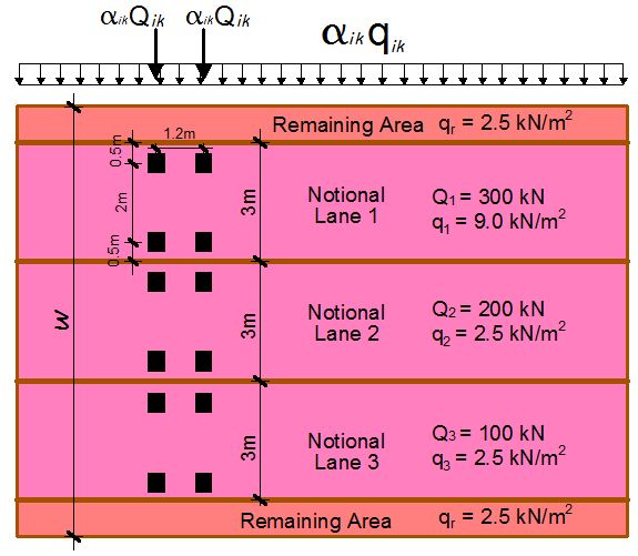
The code specifies four load models for vertical loads on highway bridges. Among these four load models, Load Model 1 (LM1) is the one used to represent the effect of normal traffic on bridges and it is used for both local and global verifications. LM1 consists of tandem axle loads (TS) which are concentrated loads applied in the longitudinal direction of the bridge, and uniformly distributed loads (UDL’s) which are applied both transversely and longitudinally. The values of the loads depends on the notional lanes on which they are applied unlike BS 5400 which uses lane factors. (See more on the paper uploaded). It is however pertinent to point out that LM1 is an artificial model and does not represent the weight of real vehicles. The models are created and calibrated based on traffic data collected in France between 1980 and 1994, and the effects they induce on bridge decks are similar to that induced by real traffic. See the form of LM1 below.
In the paper downloadable in this post, a 15.0m single span bridge simply supported between two abutments (the first picture on this post) is subjected to LM1 and analysed as static load using Staad Pro software. The bridge has a deck that is 10.1m wide and a carriageway that is 7.2m wide. The reinforced concrete slab is supported by five precast beams (girders) and the aim of the analysis is to find out the effects of the traffic load on the girders. The load was arranged to induce the worst effect on the first and second girders. The finite element analysis results obtained were very comparable to the ones obtained using other rational and computational methods.
Relevant Pictures from Analysis
(a) Another 3D view of the bridge (Modelled using Autodesk Revit 2009)
(b) A 2D elevation view of the bridge
(c) Section through the bridge deck
(d) Division of the carriageway into notional lanes
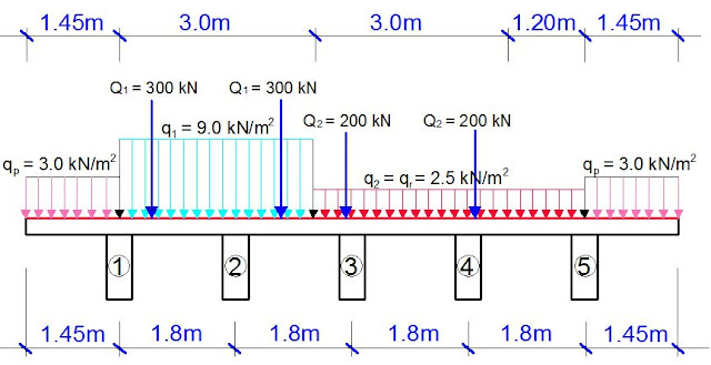
(e) Sectional view of the notional lanes, remaining area, and the pedestrian areas
(f) Finite element modelling of the bridge deck on StaadPro V8i
(g) Loading of the bridge with LM1 (including crowd load)
(h) Full 3D Model of the bridge deck on Staad Pro
(i) Bending moment diagram of the girders due to LM1
(j) Shear force diagram of the girders due to LM1
To download the full loading, analysis, and results paper, click HERE.
For more interesting interactions, visit our Facebook page at
www.facebook.com/structville


Your comments are highly welcome.
Nice one
Thank you
This is great. Keep it up
Indeed you are doing very well and educating engrs. even more than what are being done in the university. Keep it up.
Thank you Joseph. I am very grateful and we will keep working hard.
Thank you very much.
• Fantastic website. Plenty of helpful info here. I’m sending it to some friend’s and additionally sharing in delicious. And of course, thanks to your sweat!Reverse Engineering in India
Point Cloud to BIM conversion in US
Energy Analysis in India
Structural Analysis in India
I have spent much time here today as the site worth much time. Thanks for the good job. It really help me in staying safe at home this time. Much love, Engr. Continue to soar higher
Thank you… Continue to stay safe
Hello Engineer, will the girder be designed as prestressed with tendons or as a normal reinforced concrete beam?
The girders can be prestressed or constructed with normal reinforced concrete. However, in this article, normal reinforced concrete was had in mind.
Engr I think the girders are not deep enough say 1.4m deep would be fine