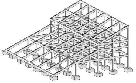
The most common construction concept of sports stadiums today is a composite type where usually precast concrete terrace units (seating decks) span between inclined (raker) steel or reinforced concrete raker beams and rest on each other, thereby forming a grandstand.
The raker beams are usually formed in-situ with the columns of the structure, or sometimes may be preferably precast depending on site/construction constraints. This arrangement usually forms the skeletal frame of a stadium structure.
A typical section through the grandstand and the L-shaped seating unit are shown in Figures 1 and 2 respectively.
This process was used in the construction of Cape Town Stadium South Africa, for the 2010 World cup (see Figure 3);
In this article, a raker beam isolated from a double-tiered reinforced concrete grandstand (see Figure 1) has been presented for the purpose of structural analysis and design. Each grandstand frame has precast L-shaped seating terrace units that span in between reinforced concrete raker beams inclined at angles between 20° – 22° with the horizontal. The raker beams are spaced at 7m centre to centre.
Crowd live loads and other loads are transferred from the seating units to the raker beams, which then transfers them to the columns and then to the foundations. Loads from the service and concourse areas are also transferred using the same load path.
The details of the structure and the loading on the first tier are shown below;

Loading on the precast seating units
Permanent Actions
Self-weight of the 7m precast seating deck (see Figure 2)
(GK1) = (25 × 0.25 × 0.15 × 7) + (25 × 0.95 × 0.15 × 7) = 31.5 kN
Weight of finishes, rails, seats (GK2) = (2 × 0.95 × 7) = 13.3 kN
Variable Actions
Imposed load for structural class C5 (qK) = 5 kN/m2
Total imposed load for seating unit (QK) = (5 × 0.95 × 7) = 33.25 kN
Total action on L-shaped seating terrace unit at ultimate limit state by Eurocode 2
(PEd) = 1.35Σ(GKi) + 1.5QK = 1.35(44.8) + 1.5(33.25) = 110.355 kN
Loading on the raker beams
Height of beam = 1200mm
Width of beam = 400mm
Self weight of raker beam
Concrete own weight (waist area) = 1.2m × 0.4m × 25 kN/m3 = 12.00 kN/m (normal to the inclination i.e. in the local direction)
Height of riser in the raker beam = 0.4m;
Width of tread in the raker beam = 0.8m;
Angle of inclination (𝛼) = 20.556°
Stepped area (risers) = ½ × 0.4 × 25 = 5 kN/m (in the global direction)
For purely vertical load in the global y-direction, we convert the load from the waist of the beam by;
UDL from waist of the beam = (12.00 × cos 20.556°) = 11.236 kN/m
Total self weight (Gk) = 11.236 + 5 = 16.235 kN/m
Self weight of raker beam at ultimate limit state;
n = 1.35Σ(GKi) = 1.35 × 16.235 = 21.917 KN/m
Load from precast seating units
End shear from precast seating unit = PEd/2 = 110.355/2 = 55.1775 kN
Total number of the precast seating units on the beam = 24/0.8 = 30 units
For intermediate beam supporting seating units on both sides;
Total number of precast seating units = 2 × 30 = 60 units
Therefore, the total shear force transferred from the seating units to the raker beam = 55.1775 × 60 = 3310.65 kN
Equivalent uniformly distributed load in the global direction at ultimate limit state = 3310.65/24 = 137.94 kN/m
Total load on intermediate raker beams at ultimate limit state in the global direction = 137.94 + 21.917 = 159.857 kN/m
Structural Analysis
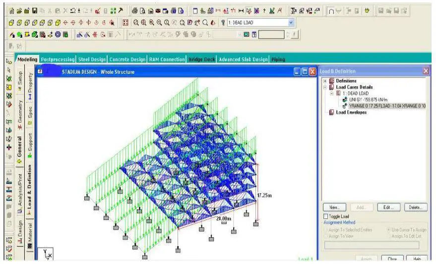
A full 3D Staad Pro Model of the grandstand is shown in Figure 5;

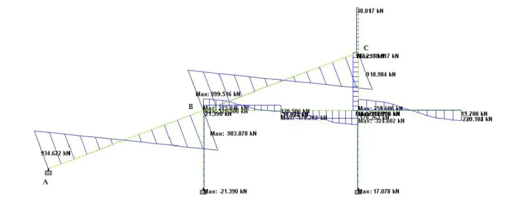
The raker beam was analysed for the loading obtained as shown above. Due to its inclination, it was subjected to significant bending, axial, and shear forces. The internal stresses are shown below;


The summary of the internal stresses in the raker beams is shown in the Table below;

Structural Design
The structural design of the raker beam using EN 1992-1-1 has been carried out and all the parameters used in the, and steps followed are shown below in the subsequent sections.
Design compressive of concrete fck = 35 N/mm2
Yield strength of steel fyk = 460 N/mm2
bw = 400mm; h = 1200mm; Cc = 40mm
Flexural Design of span AB (MABspan)
MEd = 948.078 kNm
d = h – Cc – ϕ/2 – ϕlink
d = 1200 – 40 – 16 – 10 = 1134 mm
k = 𝑀𝐸𝑑/𝑓𝑐𝑘 𝑏𝑑2 = (948.078 × 10⁶)/35 × 400 × 11342 = 0.0527
Since k < 0.167 No compression reinforcement required
z = d[0.5+ √(0.25−0.882𝐾)] = z = d[0.5 + √(0.25 − 0.882(0.0527)] = 0.95d
𝐴𝑠1 = 𝑀𝐸𝑑/0.87𝑓𝑦𝑘𝑧 = (948.078 × 10⁶)/0.87 × 460 × 0.95 × 1134 = 2199 mm2
Provide 5Y25mm BOT (ASprov = 2450 mm2)
To calculate the minimum area of steel required; (Table 3.1 EC2)
fctm =3.2099 N/mm2
As,min = 0.26 × fctm/fyk × bw × d = 0.26 × 3.2099460 ×400 × 1134 = 822.962 mm2
Check if ASmin < 0.0013 × bw × d (589.68 mm2)
Therefore, As,min = 822.962 mm2
Check for Deflection
Since the span is greater than 7m, allowable span/depth ratio = 𝛽𝑠 × 31.842 × 7000𝐿 = 1.11 × 31.842 × (7000/12816) = 19.374
Actual deflection L/d = 12816/1134 = 11.301
Since 11.301 < 19.374, deflection is ok.
Flexural Design of support A (MA);
MEd = 1967.54 kNm
k = 0.1093; la = 0.8919; AS1 = 4861 mm2; ASmin = 822.9785 mm2
Provide 4Y32mm + 4Y25mm TOP (ASprov = 5180 mm2)
Flexural Design of support B (MB);
MEd = 2283.18 kNm
k = 0.1268; la = 0.8717; AS1 = 5772 mm2; ASmin = 822.9785 mm2
Provide 6Y32mm + 4Y20mm TOP (ASprov = 6080 mm2)
Flexural Design of span BC (MBCspan)
MEd = 1249.787 kNm
k = 0.0694; la = 0.9345; AS1 = 2947mm2; ASmin = 822.9785 mm2
Provide 5Y25mm + 2Y20mm BOT (ASprov = 3083 mm2)
Shear Design
Let us consider support B
VEd = 983.88 kN; NEd = 339.376 kN (Tension)
Note that due to the tensile axial force in the section, the second term of VRd equation assumes a negative value.
𝜌1 = 0.0134; 𝜎𝑐𝑝 = − 0.7070 N/mm2; vmin = 0.3504 N/mm2; VRd = 230.6532 kN
Since VRd,c < VEd, shear reinforcement is required
Assuming that the strut angle 𝜃 = 21.8° v1 = 0.5160; fcd = 19.8450 N/mm2; z = 0.9d = 1020.6 mm;
VRD,max = 1440.64 kN
Since VRD,max > VEd
𝐴𝑠𝑤/S = 0.9635
Trying 3Y10mm @ 200mm c/c (235/200 = 1.175)
1.175 > 0.9153 Hence shear reinforcement is ok.
The design results show that the effect of axial force was not very significant in the quantity of shear reinforcement required. Asv/Sv ratio of 1.175mm (3Y10mm @ 200 c/c) was found to satisfy shear requirements at all sections. The greatest quantity of longitudinal reinforcement was provided at the intermediate support with a reinforcement ratio of 1.3404%. The provided reinforcement was found adequate to satisfy ultimate and serviceability requirements.
It is worthwhile to observe the variation in the nature of axial forces on the beams (i.e from compressive to tensile). The effect can be more significant when using BS 8110-1:1997 for design than Eurocode 2 (EN 1992-1-1).
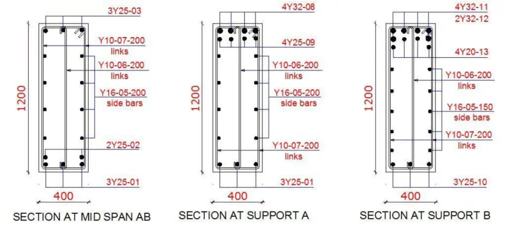
You can view some sections of the reinforced concrete raker beam below;


To download the full calculation sheet (PDF), click HERE


Father Ranks…. Baba you are the deal, the real deal
Father Ranks…. Baba you are the deal, the real deal
Biggest boss I appreciate.
This difficult staadpro
• You truly helped me understand this topic with your well researched post, thanks for all the good work.Shop Drawings Preparation in India
Fabrication Drawings preparation in India
MEP F modelling in India
Interference Analysis in India
COBie adaptation in India
Construction Documentation in India
Hi, I wanted to ask , what about dynamic loads and its influence-frequencies ect?
Thanks