Rigid frames, rigid planar shear walls, coupled shear walls, and cores are usually employed for the bracing system of a multi-storey building. These different units contribute to the overall resistance of the system, but their contributions can be very different both in weight and in nature, so it is essential for the designer to know their behaviour in order to achieve an optimum bracing system (Zalka, 2013).
The effect of wind becomes very influential as a building gets taller. Under the action of wind, vertical structures are subjected to load regimes which are often modelled as lateral (horizontal) loads, and as a result, lateral deflections are induced in the building (sway). It is very important to consider this behaviour in a tall building from both statics and dynamics perspective, in order to guarantee the performance of the structure while in use.
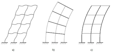
Rigid frames are very significant in the structural behaviour of buildings. They possess all the three basic stiffness characteristics, i.e., they have local bending stiffness, global bending stiffness and shear stiffness. Under lateral loads, the behaviour of frames can be complex, because they undergo both bending and shear deformations. Hence, the behaviour of frames in resisting lateral loads may be characterised by three types of stiffnesses and corresponding deflection types which are;
(a) Shear deformation
(b) Global bending
(c) Local bending
In a paper downloadable from this post, a twenty storey multi-storey rigid frame was subjected to a uniformly distributed wind load of 5.05 kN/m calculated by using the Eurocodes. The deflection behaviour of the rigid frame was investigated using a manual method proposed by Zalka (2013), and computer-based method (finite element analysis).
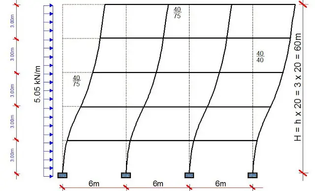
The disposition of the multi-storey frame is shown below;
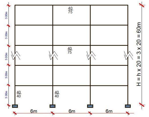
The properties of the building are as follows;
| Property | Value |
| Storey height (h) | 3 m |
| Total height of building (H) | 60m |
| Dimension of beams (d x b) | 750 mm x 400 mm |
| Dimension of columns (d x b) | 400 mm x 400 mm |
| Width of each bay (L) | 6 m |
| Modulus of elasticity of concrete (E) | 25 kN/mm2 |
Geometrical Properties of the frame
Second moment of area of beams IB = (bd3)/12 = (0.4 × 0.753)/12 = 0.0140625 m4
Second moment of area of columns IC = (bd3)/12 = (0.4 × 0.43)/12 = 0.0021333 m4
Flexural rigidity of beams EIb = 25 × 106 × 0.0140625 = 351562.5 kNm2
Flexural rigidity of columns EIC = 25 × 106 × 0.0021333 = 53333.333 kNm2
Shear stiffness of beams = KB = ∑(12EIb)/(Lih) = 3 × [(12 × 351562.5 )/(6 × 3)] = 703125 kN
The part of the shear stiffness associated with the columns is;
KC = ∑(12EIC)/h2 = 4 × [(12 × 53333.333 )/32] = 284444.443 kN
From the above, the reduction factor r can be defined as;
r = (KC )/(KB + KC) = (284444.443 )/(703125 + 284444.443) = 0.2880
The shear stiffness of the frame work can now be defined as;
K = KB × r = 703125 × 0.2880 = 202500 kN
For the local bending stiffness (EI = EIC.r), the sum of the moment of areas of the columns should be produced and multiplied by the reduction factor r. As the bays of the frame are identical, the second moment of area of one column is simply multiplied by n and r.
I = r∑IC = 4 ×0.2880 × 0.0021333 = 0.002457216 m4
The second global moment of area Ig is given by; Ig = ∑Ac,iti
Where Ac,i is the cross-sectional area of the ith column, and ti is the distance of the ith column from the centroid of the cross-sections.
Ig = ∑Ac,iti = 0.4 × 0.4 × (92 +32 + 32 + 92) = 28.8 m4
The total second moment of area for the bending stiffness (If) is given by;
If = IC.r + Ig = 28.8 + 0.002457216 = 28.8024 m4
The parameters S, ?, and ?H are also needed for the calculation of the maximum deflection;
S = 1 + (IC.r)/Ig = 1 + (0.002457216)/28.8 = 1.00008532 ≈ 1.0
? = √bs = √(K/EI) = √[202500/(25 × 106 × 0.002457216)] = 1.8156
Therefore ?H = 1.9485 × 60 = 108.936
With the above auxiliary quantities, the maximum total deflection of the frame work can now be calculated;
ymax = y(H) = (wH4/8EIf) + (wH2/2KS2) – wEI/(K2S3) × [((1 + ?Hsinh?H)/cosh?H) – 1]
yb(H) = wH4/8EIf = (5.05 × 604)/(8 × 25 × 106 × 28.8024) = 0.01136 m
ys(H) = wH2/2KS2 = (5.05 × 602)/(2 × 202500 × 12) = 0.044889 m
yi(H) = wEI/(K2S3) × [((1 + ?Hsinh?H)/cosh?H) – 1] = (5.05 × 25 × 106 × 0.002457216) / (2025002 × 13) × [(1+ 108.936 sinh(108.936)) /cosh(108.936) – 1] = 0.00082413 m
ymax = 0.01136 + 0.044889 – 0.00082413 = 0.055424 m = 55.424 mm
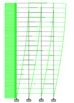
From the results of the two methods employed, it is observed that the value obtained from the manual method gave a lower value for the top deflection of the building. The maximum deflection from the finite element was 60.441mm, while the result from manual calculation was 55.524mm. This shows that the result from the finite element analysis is about 8.135% greater than that of the manual method. This offers great insight for the speedy check of computer-based processes and results.
An excerpt picture from finite element analysis is shown below;
To download the paper in PDF format, click HERE

