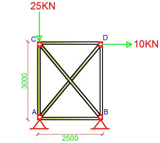
An indeterminate truss is supported and loaded as shown above, using the direct stiffness method, obtain the displacements, support reactions, and internal forces that are induced in the members due to the externally applied loads, (EA = Constant, dimensions in mm).
[the_ad id=”498″]
Summary of Procedure
(1) Establish the x and y global coordinate system. The origin is usually located at the joint for which the coordinates for all the other joints are positive.
(2) Identify each joint and member numerically, and arbitrarily specify the near and far ends of each member symbolically by directing an arrow along the member with the head directed towards the far end.
(3) Specify the two code numbers at each joint, using the lowest numbers to identify unconstrained degrees of freedom, followed by the highest numbers to identify the constrained degrees of freedom.
For the truss that is loaded as shown above, there are four unconstrained degrees of freedom which occur at nodes ② and ③. The displacements are the horizontal and vertical translations which have been labelled from 1 – 4 and represented by the arrow heads at those nodes. The members have also been labelled accordingly with their numbers enclosed in a box (see figure above). Also notice that the unconstrained degrees of freedom have labelled first. The aim of this is to simplify the arrangement of the structure’s stiffness matrix.
Computation of member global stiffness matrix
Without much attention to the derivation, the stiffness matrix is given by;
[k] =[TT][k’][T] ————— (1)
Where;
K’ = member stiffness matrix which is of the same form as each member of the truss. It is made of the member stiffness influence coefficients, k’ij
T = Displacement transformation matrix
TT = This transforms local forces acting at the ends into global force components and it is referred to as force transformation matrix which is the transform of the displacement transformation matrix [T].
When the equation is solved, the global member stiffness matrix is obtained which is given by;
Where;
l = cos θ;
m = sin θ;
L = Length of member
The global stiffness of each member is given below;
The general stiffness matrix of the structure [KT] is given by;
[KT]= [K1] + [K2] + [K3] + [K4] + [K5] + [K6]
This now yields an 8 x 8 matrix which represents all the degrees of freedom in the truss both unconstrained (1-4) and constrained (5-8).
Since the unconstrained degrees of freedom are at points 1-4, we can therefore compute the deformation at such nodes using the relation below;
[P] = [K][u]
Where [P] is the vector of joint loads acting on the truss, [u] is the vector of joint displacement and [k] is the global stiffness matrix. On partitioning the above stiffness matrix, the relationship for this problem is as given below;
On solving;
In the same vein, this same relationship can help us compute the support reactions;
On solving;
You can also realise that the obtained support reactions satisfy equilibrium requirements in the structure.
∑Fy = 0 ( i.e 12 + 13 = 25 KN)
∑Fx = 0 ( i.e 7.5662 + 2.4338 = 10 KN)
Internal Axial Forces
For computing the internal forces in the members, the following relationship is used;
[N] = [T][K’][u]
Which when expanded yields;
The axial forces in the members are now as given below;


Nice Content Thanks for sharing .. BIM Consulting
BIM Solutions
BIM Solutions in UK
Shop Drawings Preparation in UK
Fabrication Drawings preparation in UK