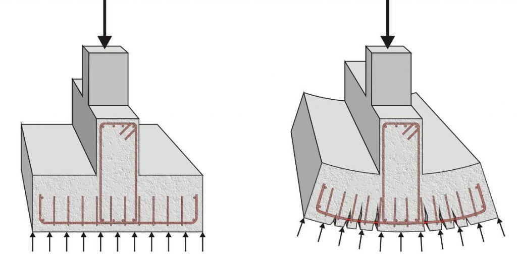
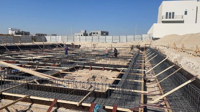
Continuous beam and slab strip footings normally consist of inverted T-beams that are used to support a series of columns or continuous walls. They are a cheaper alternative to raft foundations and can be used where individual pad foundations will overlap or where the soil is expected to undergo differential settlement or excessive shrinkage and swelling. The design of a continuous beam and slab strip footing involves the design of the base slab and upstand beam by providing adequate concrete sections and reinforcements to resist the earth pressure reaction from the applied load.

The design presented here is an excerpt from my final year project ‘Structural Analysis and Design of 35,000 Capacity Reinforced Concrete Stadium’. After the analysis and design of the superstructure (see a section of the stadium in the picture below), it was realized that a very large magnitude of axial loads and moments are being transferred to the foundation.
Foundations must be designed to resist geotechnical and structural failure, and at the same time should be economical. The ultimate bearing capacity of the supporting soil at 2.00m depth was very good at 380 KN/m2 (gravely sand), so a shallow foundation was adopted.
However, adopting a pad footing proved very uneconomical given the large area of excavation required (columns are spaced at 6.0m), and the depth of concrete needed to handle shear forces was much. Raft foundation proved to be too expensive for soil with such a good bearing capacity.
After much consideration, it was realized that chaining the columns continuously will do the trick, but at the same time, it is possible to combine the slab with upstand beams running continuously along the axis of the column. The whole aim was to reduce the great quantity of concrete that would have been required to control diagonal shear by using shear reinforcements (stirrups) in the beams. This eventually proved to be much cheaper.
In the excerpts of the design presented below, the following data were used;
Concrete grade = 30 N/mm2
Yield strength of reinforcement = 460 N/mm2
Concrete cover of reinforcement = 50mm
Bearing capacity of soil = 380 kN/m2
For this post, let us consider an axis from the structure in which the intermediate columns approximately have equal ultimate axial loads of 3081.075 kN while the end columns have an axial load of 1680.3 kN (see Figure below).
From the symmetrical arrangement of the loads, it is quite obvious that the centroid will pass through the middle column, hence, soil pressure can be assumed to be uniform under the whole length of the footing.
Dimension of all columns = (500 x 300 mm)
Total Ultimate Limit State (ULS) Load = 2(1680.3) + 5(3081.075) = 18765.975 kN
Axial load conversion factor to Serviceability Limit State (SLS) α = 1.45
NSLS = 18765.975/(1.45 ) = 12942.05 kN
Assume 12% of service load to be the self-weight (SW) of the footing
SW = (12/100) × 12942.05 = 1553.04 kN
Area of footing required Areq = NSLS+ SW /(Bearing Capacity) = (12942.05 + 1553.04)/380 = 38.14 m2
Taking a 36.3m long base, the width B = 38.14/36.3 = 1.051 m
Therefore, provide a 1.1 m x 36.3m base (Aprov = 39.93 m2)
Let the thickness of the footing be 1100mm
Earth Pressure intensity (q) = N/Aprov = (18765.975 KN)/(39.93 m2 ) = 469.97 kN/m2
Design of the footing cantilever slab portion (per meter strip)
Note that the bending moment in the slab is maximum at the face of the column (in this case at the face of the upstand beams)
Width of the upstand beam = 500mm = 0.5m
Hence, Moment arm (jxx) = (1.1– 0.5)/(2 ) = 0.30 m
Assume depth of slab h = 300mm, concrete cover (Cc) = 50mm and assuming that (ϕ) Y20mm bars will be used;
Hence, the effective depth (d) = h – Cc – ϕ/2 = 300 – 50 – (20/2) = 240mm
Mx-x = (q × jxx2) / 2 = (469.97 × 0.32)/2 = 21.14 KN.m
k = M/(Fcubd2 ) = (21.14 × 10⁶) / (30 × 1000 × 2402 ) = 0.012
k < 0.156, no compression steel needed
Lever arm (la) = 0.5 + (0.25 – K/0.9)0.5 Hence la = 0.95
The area of tenseion steel required; ASreq = M/(0.95fy.la.d ) = (21.14 × 10⁶) / (0.95 × 460 × 0.95 × 240) = 212.17 mm2
ASmin = 0.13bh/100 = (0.13 × 1000 × 300)/100 = 390 mm2
Therefore, Provide Y12 @ 200 mm c/c (Asprov = 566 mm2/m)
Distribution bars on slab
ASmin = 0.13bh/100 = (0.13 × 1000 × 300)/100 = 390 mm2
Therefore, Provide Y12 @ 250 mm c/c (Asprov = 452 mm2/m)
Shear design of slab
The concrete resistance shear stress (Vc) = 0.632 × (100As/bd)1/3 × (400/d)1/4
Vc = 0.632 × [(100 × 566)/(1000 × 240)]1/3 × (400/240)1/4
Vc = 0.632 × 0.617 × 1.136 = 0.443 N/mm2
For Fcu = 30N/mm2
Vc = 0.443 × (30/25)1/3 = 0.470 N/mm2
Critical diagonal shear force at ‘d’ from the face of support (Q)
Q = q (jxx – d)
Therefore the shear force Q= 467.97 × (0.30 – 0.24) = 28.078 KN/m
The resultant shear stress V = (28.078 × 10³)/(1000 × 240) = 0.1169 N/mm2
We can see that V < Vc, ie (0.1169 N/mm2 < 0.470 N/mm2)
Hence, diagonal Shear is ok
A little consideration will show that punching shear at 1.5d from the face of column is also ok (falls outside the footing dimensions). Hence design is ok.
Design of ground longitudinal upstand beam
Width of beam = width of column = 500mm = 0.5m
Uniformly distributed soil reaction on beam = Earth pressure intensity × Width of footing = 467.97 x 1.1 = 514.77 KN/m
Bottom Reinforcement Design (Column Support Points)
Total depth of beam = 1100mm
Effective depth (d) = 1100 – 50 – 16 – 10 = 1024mm (assuming the use of Y32mm bars and Y10mm links)
Design Moment (M) = 1960.09 kN.m
k = M/(Fcubd2 ) = (1960.09 × 106)/(30 × 500 × 10242) = 0.124
Since k < 0.156, no compression steel needed
Hence the lever arm, la = 0.5 + (0.25 – K/0.9)0.5 Hence la = 0.834
The area of tension steel required; ASreq = M/(0.95Fy.la.d ) = (1960.09 × 106)/(0.95 × 460 × 0.834 × 1024) = 5252 mm2
ASmin = 0.26bh/100 = (0.26 × 500 × 1100)/100 = 1430 mm2
Provide 6Y32mm + 2Y25mm BOT (Asprov = 5806 mm2) around the penultimate supports. (See detailed drawings)
Central Column Support Bottom Reinforcement Design
M = 1603.71 kN.m
k = M/(Fcubd2) = (1603.71 × 106) / (30 × 500 × 10242) = 0.1019, k < 0.156, no compression steel needed.
la = 0.5 + (0.25 – K/0.9)0.5 Hence la = 0.869
The area of tension steel required; ASreq = M/(0.95Fy.la.d ) = (1603.71 × 106)/(0.95 × 460 × 0.869 × 1024) = 4124 mm2
ASmin = 0.26bh/100 = (0.26 × 500 × 1100)/100 = 1430 mm2
Provide 4Y32mm + 3Y25mm (Asprov = 4689 mm2) at the central column support. (See detailed drawings)
Top Reinforcement Design (Beam Span Design)
M = 1440.08 kN.m
k = M/(Fcubd2) = (1440.08 × 106/(30 × 500 × 10242) = 0.0916
la = 0.5 + (0.25 – K/0.9)0.5 Hence la = 0.885
The area of tension steel required; ASreq = M/(0.95Fy.la.d ) = (1440.08 × 106)/(0.95 × 460 × 0.885 × 1024) = 3387.5 mm2
ASmin = 0.18bh/100 = (0.18 × 500 × 1100)/100 = 990 mm2
Provide 4Y32mm + 2Y16mm (Asprov = 3618 mm2)
Mid-span Sections Design
M = 802.71 kN.m
k = M/(Fcubd2)) = (802.71 × 10⁶)/(30 × 500 × 10242) = 0.051; k < 0.156, no compression steel needed
la = 0.5 + (0.25 – k/0.9)0.5 Hence la = 0.939
The area of tension steel required; ASreq = M/(0.95Fy.la.d ) = (802.71 × 10⁶)/(0.95 × 460 × 0.939 × 1024) = 1910 mm2
ASmin = 0.18bh/100 = (0.18 × 500 × 1100)/100 = 990 mm2
Provide 4Y25mm + 2Y16mm (Asprov = 2366 mm2)
Longitudinal Face Side Bars
Provide Y16mm @ 200mm c/c both faces
Shear design of the longitudinal ground beams
Punching Shear at column face
Taking the maximum shear force for punching shear verification at column face
Punching shear at column face Vf = (1870 × 3.4846)/3.6346 = 1792.8 kN
Punching shear stress = (1792.8 × 1000)/(500 × 1024) = 3.5016 N/mm2
We can see that 3.5016 N/mm2 < 0.8√fcu < 5 N/mm2
Therefore, the depth of the section is adequate for shear.
Maximum shear force on the footing = 1870.99 kN
The shear force at ‘d’ from the face of the column, Vd = (1870.99 × 2.4606)/3.6346 = 1266.64 kN (calculation was done looking at the shear force diagram)
The shear stress v = Vd/bd = (1266.64 × 1000)/(500 × 1024) = 2.474 N/mm2
The concrete resistance shear stress (Vc) = 0.632 × (100As/bd)1/3 × (400/d)1/4
Hence, Vc = 0.632 × [(100 × 5806)/(500 × 1024)]1/3 × (400/1024)1/4
Vc = 0.632 × 1.032 × 1 = 0.652 N/mm2
For Fcu = 30 N/mm2, Vc = 0.652 × (30/25)1/3 = 0.692 N/mm2
Hence shear reinforcement is required
Trying 4 legs of Y10mm, we have;
Spacing Sv = (0.95 × Fyv × Asv)/(bv (v – Vc)) = (0.95 × 460 × 314)/(500 (2.474 – 0.692)) = 154 mm
Maximum spacing = 0.75d = 0.75 × 1024 mm = 768 mm
Provide 4Y10mm @ 150mm c/c links as shear reinforcement
The extent of shear links
Shear stress of nominal links Vn = [(Asv/Sv) × 0.95fy + (bw × Vc)] d
Concrete Resistance shear stress Vc = 0.692 N/mm2
Vn = [(236/300) × 0.95 × 460 + 500 × 0.692) × 1024 × 10-3 = 706.326 KN (Taking a nominal shear reinforcement of 3Y10 @ 300mm)
Extent of shear links Sn = (Vd – Vn)/q + d Extent of shear links Sn = (1266.64 – 706.326)/(514.77 + 1.024) = 2.112 m
Therefore, stop main shear links(4Y10mm @ 150mm) i.e. at 2.2 m from face of column and provide nominal reinforcement of 3Y10 @ 300mm till the point of zero shear force.
Shear force at the central column support point = 1574.01 kN
The shear force at d from the face of column, Vd = (1574.01 × 1.88369)/3.05769 = 969.668 kN
The shear stress v = Vd/bd = (969.668 × 1000)/(500 × 1024) = 1.893 N/mm2
The concrete resistance shear stress (Vc) = 0.632 × (100As/bd)1/3 × (400/d)1/4
Vc = 0.632 × ((100 × 4689)/(500 × 1024))1/3 × (400/1024)1/4
Vc = 0.632 × 0.9711 × 1 = 0.613 N/mm2
For Fcu = 30 N/mm2, Vc = 0.613 x (30/25)1/3 = 0.6517 N/mm2
Hence shear reinforcement is required
Trying 4 legs of Y10mm, we have;
Spacing of links Sv = (0.95 × Fyv × Asv)/(bv (v – Vc)) = (0.95 × 460 × 314)/(500(1.893 – 0.6517)) = 221.087 mm
Maximum spacing = 0.75d = 0.75 x 1024 =768 mm
Provide 4Y10mm @ 200mm c/c links as shear reinforcement
The extent of shear links
Shear stress of nominal links Vn = [(Asv/Sv) × 0.95fy + (bw × Vc)] d
Vc = 0.6517 N/mm2
Vn = [( 236/300) × 0.95 × 460 + 500 × 0.6517)] × 1024
Hence, Vn = 685.69 kN (Taking a nominal shear reinforcement of 3Y10 @ 300mm)
Extent of shear links Sn = (Vd – Vn)/q + d
Extent of shear links Sn = (698.665 – 685.69)/514.77 + 1.024 = 1.049 m
Stop shear links at 1.1 m from the face of the column and provide nominal reinforcement = 3Y10 @ 300mm
The picture below shows the section through the first span of the continuous footing;
The picture below shows the section through the second support of the continuous footing;


is there any design of raker beam
http://structville.blogspot.com.ng/2016/04/analysis-and-design-of-continuous-rc.html?m=1
Yes… It is a topic on this blog…. See the link above
Thanks for sharing nice content .. Structural Analysis in India
Shop Drawings Preparation in India
Fabrication Drawings preparation in India
MEP F modelling in India
Interference Analysis in India
COBie adaptation in India
Construction Documentation in India
Thanks for sharing this . I find it very useful in my work on similar on similar topic
I came across a good example of this problem. I actually try to design this foundation type. Could you let me know of any book illustrating solutions for the same footing type? Thanks
The analysis to obtain shear and moment is misleading. It is tempting to analyze continuous footing as if it were tee beam at upper floors, where we will normally have UDL applied on the beam and we go ahead with determining the axial forces, shear and bending moments. For footing, however, the soil reaction acts as UDL upward (if uniform pressure) and the column loads are already the reactions. In this case, larger bending moment is often around the mid-span; requiring more reinforcement compared to locations of column. Another thing is when the exterior axial loads are not significantly smaller than interior column axial loads, the interior columns may experience uplifting as the exterior loads pressuring downward. This is mechanically and geometrically possible due to continuity provided by the footing slab and girder.
I would love to hear other views.