1.0 Introduction
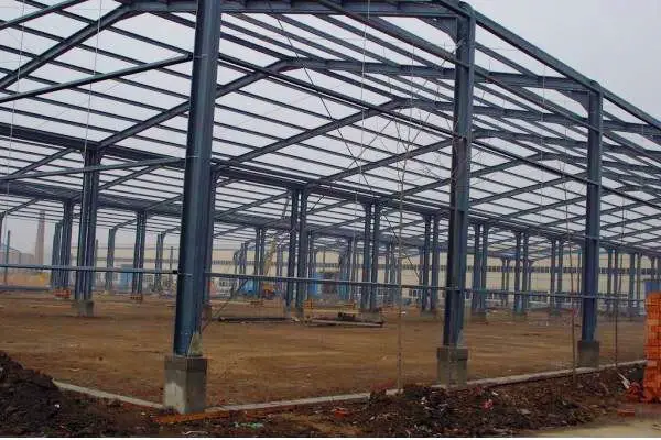
Industrialization is one of the major keys to development and sustainable economy. Industrial structures are usually very easy to identify because of their unique features that are quite different from residential or commercial buildings. Engineers are often tasked with analysing and designing industrial frames, and to simplify the analysis for manual calculations, they are usually idealised as 2D plane frames.
2.0 Solved Example
In this post, a gable industrial frame structure is subjected to a load regime as shown below. The frame is hinged at point D, and it is desired to obtain the internal forces (bending moment, axial forces, and shear forces) due to the externally applied load.
N/B: In practical construction, it is not advisable to hinge the structure at the apex due to the problem of excessive deflection and stability of the frame.
Solution
(a) Support Reactions
Geometrical Properties
Angle of inclination of the rafter
θ = tan-1(2.5/6) = 22.619°
cos θ = 0.923
sin θ = 0.385
Length of rafter (z) = sqrt(62 + 2.52) = 6.5m
Notations:
Example: NCR = Axial Load at point C, just to the Right
Let ∑MG = 0
12Ay – [(10 × 122)/2] – (25 × 11) + (7 × 4) – (16 × 1) = 0
12Ay = 983
Ay = 81.917 kN
Let ∑MDL = 0
6Ay – 8Ax – (25 × 5) – (7 × 4) – [(10cos22.619° × 6.52)/2] = 0
6(81.917) – 8Ax – (25 × 5) – (7 × 4) – [(9.23 × 6.52)/2] = 0
8Ax = 143.518 kN
Ax = 17.939 kN
Let ∑MA = 0
12Gy – [(10 × 122)/2] – (25 × 1) – (7 × 4) – (16 × 11) = 0
12Gy = 949
Gy = 79.083 kN
Let ∑MDR = 0
6Gy – 8Gx – (16 × 5) – [(10cos22.619° × 6.52)/2] = 0
6(79.083) – 8Gx – (16 × 5) – [(9.23 × 6.52)/2] = 0
8Gx = 199.515 kN
Gx = 24.939 kN
Equilibrium Check
All downward vertical forces = (10 × 12) + 25 + 16 = 161 kN
Upward reactive forces = 81.917 + 79.083 = 161 kN
All rightward horizontal forces = Ax + 7kN = 17.939 + 7 = 24.939 kN
All leftward horizontal forces = Gx = 24.939 kN
Therefore, equilibrium is ok. If you are having confusions, the post below might help.
Read Also….
Understanding Sign Conventions in Structural Analysis
(b) Internal Stresses
Section A – BB (0 ≤ y ≤ 4.0m)
(i) Bending moment
My = -Ax.y = -17.939y
At y = 0; MA = 0
At y = 4.0m; MBB = (-17.939 × 4) = -71.756 kNm
(ii) Shear Force
Qy = ∂My/∂y = -17.939 kN
(iii) Axial Force
Ny + Ay = 0
Ny = -Ay = -81.917 kN (compression)
Section 1 – BR (0 ≤ x ≤ 1.0m)
(i) Bending moment
Mx = -25.x
At x = 0; M1 = 0
At x = 1.0m; MBR = (-25 × 1) = -25 kNm
(ii) Shear force
Qx = ∂Mx/∂x = -25 kN
(iii) Axial Force
Nx – 7kN = 0
Nx = 7kN (tension)
Section BUP – CB (4 ≤ y ≤ 5.5m)
(i) Bending moment
My = -Ax.y + (25 × 1) – 7(y – 4)
At y = 4m; MBUP = -(17.939 × 4) + 25 = -46.756 kNm
At y = 5.5m; MCB = -(17.939 × 5.5) + 25 – 7(1.5) = -84.1645 kNm
Qx = -17.939 – 7 = -24.939 kN
(iii) Axial force
Ny + Ay – 25kN = 0
Ny = -81.917 + 25 = -56.917 kN (compression)
(i) Bending moment
The bending moment transferred transferred to the rafter at node C is -84.1645 kNm
Summation of vertical force transferred ∑V = Ay – 25 = 81.917 – 25 = 56.917 kN
Summation of horizontal force transferred ∑H = Ax + 7 = 17.939 + 7 = 24.939 kN
Mz = (∑V.cos22.619-9°.z) – (∑H.sin22.619°.z) – [(10cos22.619° × z2)/2] – 84.1645
Mz = 52.539z – 9.591z – 4.6154z2 – 84.1645
Mz = -4.6154z2 + 42.9425z – 84.1645
At z = 0; MCR = -84.1645 kNm
At z = 6.5m; MCB = -4.6154(6.5)2 + 42.948(6.5) – 84.1645 = -195 + 279.126 – 84.1645 = 0
Maximum span moment
Mz = -4.6154z2 + 42.9425z – 84.1645
Maximum moment occurs at the point of zero shear
∂Mz/∂z = -9.23z + 42.9425 = 0
z = 42.9425/9.23 = 4.652m
Mmax = -4.6154(4.652)2 + 42.9425(4.652) – 84.1645 = -99.882 + 199.768 – 84.1645 = 15.7215 kNm
(ii) Shear force
∂Mz/∂z = (∑V.cos22.619) – (∑H.sin22.619)
At z = 0; QCR = (56.917 × 0.923) – (24.939 × 0.385) = 42.933 kN
At z = 6.5m; QDL = [(56.917 – (10 × 6)) × 0.923] – (24.939 × 0.385) = -2.8456 – 9.6015 = -12.447 kN
(iii) Axial force
At z = 0; NCR = -(56.917 × 0.385) – (24.939 × 0.923) = -21.913 – 23.018 = -44.931 kN
At z = 6.5m; NDL = [-(56.917 – (10 × 6)) × 0.385] – (24.939 × 0.923) = 1.187 – 23.018 = -21.831 kN
Coming from the right
Section G – FB (0 ≤ y ≤ 4.0m)
(i) Bending moment
My = -Gx.y = -24.939y
At y = 0; MG = 0
At y = 4.0m; MFB = (-24.939 × 4) = -99.756 kNm
(ii) Shear Force
Qy = ∂My/∂y = +24.939 kN (note that we are coming from right to left)
(iii) Axial Force
Ny + Gy = 0
Section 2 – FR (0 ≤ x ≤ 1.0m)
(i) Bending moment
Mx = -16.x
At x = 0; M2 = 0
At x = 1.0m; MFR = (-16 × 1) = -16 kNm
(ii) Shear force
Qx = ∂Mx/∂x = -16 kN
(iii) Axial Force
Nx – 0 = 0
Section FUP – EB (4 ≤ y ≤ 5.5m)
(i) Bending moment
My = -Gx.y + (16 × 1)
At y = 4m; MFUP = -(24.939 × 4) + 16 = -83.756 kNm
At y = 5.5m; MEB = -(24.939 × 5.5) + 16 = -121.1645 kNm
Qx = 24.939 kN
(iii) Axial force
Ny + Ay – 16kN = 0
Ny = -79.083 + 16 = -63.083 kN (compression)
(i) Bending moment
The bending moment transferred transferred to the rafter at node C is -121.1645 kNm
Summation of vertical force transferred ∑V = Gy – 16 = 79.083 – 16 = 63.083 kN
Summation of horizontal force transferred ∑H = Gx = 24.939 kN
Mz = (∑V.cos22.619-9°.z) – (∑H.sin22.619°.z) – [(10cos22.619° × z2)/2] – 121.1645
Mz = 58.225z – 9.5915z – 4.6154z2 – 121.1645
Mz = -4.6154z2 + 48.6335z – 121.1645
At z = 0; MER = -121.1645 kNm
At z = 6.5m; MCB = -4.6154(6.5)2 + 48.6335(6.5) – 121.1645 = -195 + 316.1175 – 121.1645 = 0
Maximum span moment
Mz = -4.6154z2 + 48.6335z – 121.1645
Maximum moment occurs at the point of zero shear
∂Mz/∂z = -9.23z + 48.6335 = 0
z = 48.6335/9.23 = 5.269m
Mmax = -4.6154(5.269)2 + 48.6335(5.269) – 121.1645 = -128.134 + 256.2499 – 121.1645 = 6.9514 kNm
(ii) Shear force
∂Mz/∂z = -(∑V.cos22.619) + (∑H.sin22.619)
At z = 0; QCR = (63.083 × 0.923) – (24.939 × 0.385) = -58.2256 + 9.6015 = -48.624 kN
At z = 6.5m; QDL = -[(63.083 – (10 × 6)) × 0.923] + (24.939 × 0.385) = -2.8456 + 9.6015 = 6.756kN
(iii) Axial force
At z = 0; NCR = -(63.083 × 0.385) – (24.939 × 0.923) = -24.287 – 23.018 = -47.305kN
At z = 6.5m; NDL = [-(63.083 – (10 × 6)) × 0.385] – (24.939 × 0.923) = -1.187 – 23.018 = -24.205 kN
(b) Internal Stresses Diagram
(a) Bending Moment Diagram


Its a very informative article for structural engineers.
You can get free structural engineering resources from my website:
https://worldcentre.me
Thanks
Mahmood
The prerequisites inside the construction segment are exceptionally particular and Pegasus perceives these intricate business necessities inside the construction area. Corrosion prevention
I am curious to know how you got reaction values at point 1 and 2?
Business structures ought to think about economizers on their gear. Most current codes require economizers on hardware more than 15 tons in size. heating pump repair armonk
Regularly the plumber should convey at least $500,000.00 by and large risk protection, yet it isn't unprecedented for plumbers who do business plumbing to convey $3,000,000.00 in inclusion. plumber southbury
Nice post mate, keep up the great work, just shared this with my friendz oxidizers
Thank you Ubani Ranks
Thumbs up.
I designed a 60m span factory steel portal framework of upto 100m length for Chikason group Nnewi.
I used both Etabs for the analysis and Protastructure. I compared results to detail the final output.
Each column footing was about 6×2.5m area.
Our type of useless set of engineers that don’t know anything questioned my that my base is too much.
I was disappointed and I angrily explained to them what they were about to construct wasn’t a small structure, besides it was a result of analysis not guess work which they do mostly.
I also designed an overhead tank to carry 25k litres of water for them.
Anyways, kudos to you
Thank you again! Your explanation is very good and easy to understand