Last year, I made a submission here on how to carry out the thickness design of column base plates.
See post below;
Thickness Design of Column Base Plates According to EC3
Right now, we wish to check the result obtained from the manual analysis above with result from Prokon software. This present design has been carried out according to BS 5950:2000, and in this post, we will highlight all the input variables that are necessary to carry out the design, as well as the results.
Axial Load on Column
Characteristic force from permanent action Gk = 620 kN
Characteristic force from leading variable action Qk = 132 kN
Partial Factor for Loads
Permanent action γG = 1.4
Variable action γG = 1.6
At ultimate limit state;
N = 1.4Gk + 1.6Qk
N = 1.4(620) + 1.6(132) = 1079.2 kN
Column Dimensions and Properties (UC 203 x 203 x 60)
Depth (d) = 209.6mm
Width (b) = 205.8mm
Thickness of web (tw) = 9.4mm
Thickness of flange = (tf) = 14.2mm
Root radius (r) = 10.2mm
Perimeter of section = 1206.4mm
Area of section = 76.4 cm2
Base Plate Bedding Details
Strength of concrete/grout = 25 N/mm2
Step 1: Getting stared
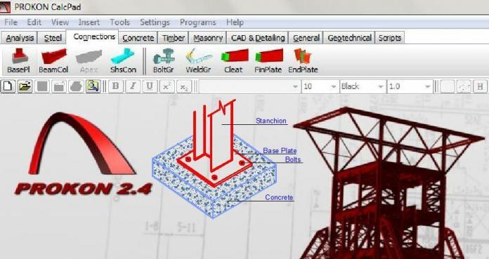
Launch the Prokon Software, go to ‘Connections Module’, and select ‘Base Plate’. The window below comes up.
This is a simple interactive interface that allows you to carry out your design in a very simple manner. As you input the design variables, the graphical representation of what you are doing comes up on the window, so that you will remain properly guided.
Step 2: Verify Design Code
At the upper left hand side of the screen, go to ‘File’, and make sure that the design code is set to BS 5950
Step 3: Select the Section Size
At the column dialog box at the upper left hand side of the screen, check the universal column symbol (see screenshot above). Now, go to the drop down list and select the appropriate column section. In this example, we are dealing with UC 203x203x60.
Step 4: Input Dimensions
As a guide, the area of base plate required should be equal to or greater than;
N/0.6fcu = (1079.2 x 1000)/(0.6 x 25) = 71946.667 mm2
It is always a good practice to allow at least 100mm from the edge of the column to the base plate.
Let us adopt base plate 350mm x 350mm (Aprov = 122500 mm2).
Now input the base plate dimensions as given below;
You will discover that the drawing below automatically appears on the window;
What this requires is for you to input the offset, in order to position the column on your desired location on the base plate. However, we want our column to centralised, and Prokon gives us that option by the click of a button. Go to the area where you input loads, and by the side of the table, click on ‘Centralise Column’. This brings the column to the centre of the base plate, and the offset value is calculated automatically for us. See the new image below;
Now, by imputing the rest of the variables, we can position the bolts to suit the design appropriately. We are offsetting the bolts 35mm from the edge of the plate. See the input and the result below;
Step 5: Define materials properties (general parameters)
From the dialog box below, define the properties of the materials to be used in the construction.
We are saying no to the use of studs because we want the column load to be transferred directly to the concrete bedding and not to the bolts. The grade of concrete and yield stress of steel selected is as given above.
Step 6: Define the loads
Since we have already factored our loads, we can input the ultimate load directly and set the load factor as unity (1.0). Alternatively, we can input the dead load and live load separately with their appropriate factor of safety, but note that they must be presented as the same load case. See below;
If you have gotten to this point without any errors, we can then click on ‘Design’ function, and the window below comes up with the design completely done;
When the plate is unstiffened, the design result above holds good, with base plate thickness of 18mm.
When the plate is stiffened, the design result below holds good, which also includes the thickness of the stiffeners, and weld designs. The plate thickness in this case reduced to 10mm.
Step 8: Detail Drawing
Click on drawing, and you will be able to see the shop drawing for the design. The images below gives the detailing for the unstiffened and stiffened plates respectively.
Conclusion
I think the result above needs no interpretation. The details are quite crystal clear and I must say that it is very impressive. It is very interesting to note that when this same base plate was designed manually using EC3 (unstiffened), we obtained a thickness of 18.447mm, and then provided a base plate of 20mm. This shows reliability of both methods for all practical purposes. You can read the manual design below just in case you missed it.
Thickness Design of Column Base Plates According to EC3
Thank you for visiting Structville today, and God bless.
E-mail your thoughts to the author: ubani@structville.com








• Hiya, I am really glad I’ve found this info. Today bloggers publish only about gossip and web stuff and this is really frustrating. A good site with exciting content, that is what I need. Thanks for making this site, and I’ll be visiting again. Do you do newsletters? I Cant find it.
BIM Implementation in India
Documentation Services in India
ANIMATION SERVICES in India
CAD to BIM conversion in India
Sometimes I use prokon its very good.