1.0 Introduction
The fin plate connection is very popular in the construction industry due to its ease of erection, and the absence of shared bolts in two sided connections. It consists of a length of plate welded to the supporting member (eg column or primary beam), and the supported member bolted to the fin plate. Technically, fin plates derive their rotational capacity from shear deformation of the bolts, and hole distortion in the fin plate and/or the beam web.
2.0 Practical Considerations and Recommended Geometry
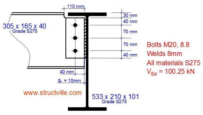
With 10mm thick fin plate in S275 steel, 8mm fillet weld to the supporting member will guard against any possibility of weld failure (CSI, 2011). Fin plates may be classified as short or long as follows;
Short tp/zp ≥ 0.15
Long tp/zp < 0.15
Where zp is the distance between the face of the support and the first line of bolts. For short fin plates, erection on site is usually more difficult, but with long fin plates, care must be taken against lateral torsional buckling, especially if the beam is laterally unrestrained.
According to SCI (2011), when detailing the joint, the following recommendations should be followed;
(1) Full strength fillet welds are provided
(2) The fin plate is positioned close to the top flange in order to provide positional restraint
(3) The depth of the fin plate is at least 0.6 times the supported beam depth in order to provide the beam with adequate torsional restraint
(4) The thickness of the fin plate or the beam web is ≤ 0.50d (for S275 steel)
(5) Property class 8.8 bolts non-preloaded are used
(6) All end and edge distances on the plate and the beam web are at least 2d
Since the depth of beam is less than 610mm, let us adopt fin plate size of 100 x 10mm
Gap gh = 10mm
Bolt rows = 3
Length of plate = 0.6 × 303.4 = 182.04mm (provide plate length = 220mm)
(i) Supported beam Bolt Shear Check
Basic requirement VEd ≤ VRd
VRd = nFv,Rd/sqrt[(1 + αn)2 + (βn)2]
Fv,Rd = (αvfubA)/γm2
For M20 8.8 bolts;
Fv,Rd = (0.6 × 800 × 245)/1.25 = 94080 N = 94.08 kN
For a single vertical line of bolt (n2 = 1, and n = n1); α = 0
β = 6z/[n1(n1 + 1)p1]
β = (6 × 30)/[3 × (3 + 1) × 70] = 0.214
Therefore;
VRd = (3 × 94.08)/sqrt[(1 + 0 × 3)2 + (0.214 × 3)2)] = 237.506 kN
VEd = 100.25 kN < 237.506 kN
Therefore bolt group is ok for shear
(ii) Fin plate in bearing
Basic requirement VEd ≤ VRd
VRd = n/sqrt{[(1 + αn)/(Fb,ver,Rd )]2 + [βn/(Fb,hor,Rd]2}
α = 0; β = 0.214
The vertical bearing resistance of a single bolt
Fb,ver,Rd = (k1αbfupdtp)/γm2
k1 = min[2.8(e2/d0) – 1.7; 2.5) = min[2.8(50/22) – 1.7; 2.5)
= min[4.66;2.5] = 2.5
αb = min[e1/3d0; (p1/3d0 – 1/4); fub/fup; 1.0]
= min[40/(3 × 22); (70/(3 × 22) – 0.25); 800/410; 1.0]
= min[0.61; 0.81; 1.95; 1.0] = 0.61
Fb,ver,Rd = (2.5 × 0.61 × 410 × 20 ×10)/1.25 = 100040 N = 100.04 kN
The horizontal bearing resistance of a single bolt
Fb,hor,Rd = (k1αbfupdtp)/γm2
k1 = min[2.8(e1/d0) – 1.7; 1.4(p1/d0) – 1.7; 2.5)
= min[2.8(40/22) – 1.7; 1.4(70/22) – 1.7;2.5)
= min[3.39; 2.75; 2.5] = 2.5
αb = min[e2/3d0; fub/fup; 1.0]
= min[50/(3 × 22); 800/410; 1.0]
= min[0.76; 1.95; 1.0] = 0.76
Fb,hor,Rd = (2.5 × 0.76 × 410 × 20 ×10)/1.25 = 124640 N = 124.64 kN
VRd = (3)/sqrt{[(1 + 0 × 3)/100]2 + [(0.214 × 3)/124.64]2) = 288.218 kN
VEd = 100.25 kN < 288.218 kN Ok
(iii) Supported Beam – Fin Plate
Shear
Basic requirement VEd ≤ VRd,min
VRd,min = min(VRd,g;VRd,n;VRd,n)
Gross section
VRd,g = (hp.tp.ffy,p)/[1.27 × sqrt(3) × γm0]
VRd,g = [(220 × 10 × 275)/(1.27 × √3 × 1.0)] × 10-3 = 275.034 kN
Net Section
VRd,n = Av,net × [fu,p / (sqrt(3) × γm2)]
Net Area = Av,net = tp.(hp – n1.d0)
Av,net = 10(220 – 3 × 22) = 1540 mm2
VRd,n = 1540 × [410 / (√3 × 1.1)] × 10-3 = 331.399 kN
Block Tearing
VRd,b = [(0.5fu,p Ant)γm2] + [fy,p Anv / (sqrt(3) × γm0)]
Net area subject to tension = Ant = tp[e2 – 0.5d0]
Ant = 10[e2 – 0.5d0]
Ant = 10[50 – 0.5 × 22] = 390 mm2
Net area subject to shear = Anv = tp[hp – e1 – (n1 – 0.5)d0]
Anv = 10[20 – 40 – (3 – 0.5) × 22] = 1250 mm2
VRd,b = [(0.5 × 410 × 390)1.1] + [(275 × 1250)/ (sqrt(3) × 1.0)] = 72681.818 + 198464.155 = 271145.973 = 271.145 kN
VRd,min = min(275.034; 331.399; 271.145 ) = 271.145 kN
VRd,min = 100.25 kN < 271.145 kN Ok
Lateral Torsional Buckling of fin plates
Basic requirement VEd ≤ VRd
tp/zp = 220/50 = 4.4 > 0.15
Therefore fin plate is short;
VRd = [(Wel,p/z) × (fy,p / γm0)]
Wel,p = (tphp2)/6 = (10 × 2202)/6 = 73333.333 mm3
VRd = [(73333.333/50) × (275 / 1.0)] = 403333.333 N = 403.333 kN
VEd = 100.25 kN < 403.33 kN Ok
Supported Beam in Shear
Gross Section
VRd,g = [Av,web × (fy,b1 / (sqrt(3) × γm0))]
Gross Area Av = ATee – btf,b1 + (tw,b1 + 2rb1) × 0.5tf,b1
ATee = (265.2 – 10.2) × 6 + (165 × 10.2) = 1530 + 1683 = 3213 mm2
Av = 3213 – (165 × 10.2) + (6 + 2 × 8.9) × 0.5 × 10.5 = 3213 – 1683 + 124.95 = 1654.95 mm2
VRd,g = 1654.95 × 275 / (sqrt(3) × 1.0) = 262758.603 N = 262.758 kN
Net Section
VRd,n = [Av,net × (fu,b1 / (sqrt(3) × γm2))]
Net area; Av,net = Av – n1d0tw,b1 = 1654.95 – (3 × 22 × 6) = 1258.95 mm2
VRd,n = 1258.95 × 410 / (sqrt(3) × 1.1) = 270918.727 N = 270.918 kN
Block Tearing
VRd,b = [(0.5fu,b1 Ant)γm2] + [fy,b1 Anv / (sqrt(3) × γm0)]
Net area subject to tension = Ant = tw,b1[e2,b – 0.5d0]
Ant = 6[40 – 0.5 × 22] = 174 mm2
Net area subject to shear = Anv = tw,b1[e1,b + (n1 – 1)p1 – (n1 – 0.5)d0]
Anv = 6[40 + (3 – 1)70 – (3 – 0.5)22] = 750 mm2
VRd,b = [(0.5 × 410 × 175)1.1] + [(275 × 750)/ (sqrt(3) × 1.0)] = 35873.9 + 119081.986 = 154955.886 = 154.955 kN
VRd,min = min(262.758; 270.918; 154.955) = 154.955 kN
VRd,min = 100.25 kN < 154.955 kN Ok
Check for welding (supporting beam)
For a beam in S275 steel;
Basic requirement; a ≥ 0.5tp
0.5tp = 0.5 × 10 = 5mm
a = 5.7mm > 0.5tp
Thank you for visiting Structville today. God bless you.







Not many writers can persuade me to their way of thinking. You’ve done a great job of doing that on many of your views here. CoBie adaptation in USA
Interference Analysis in USA
MEP F modelling in USA
Revit Modeling in USA