1.0 Introduction
Isogeometric Analysis (IGA) is a computational approach that integrates Finite Element Analysis (FEA) and Computer Aided Design (CAD). Isogeometric Analysis is developed for the purpose of utilizing the same data set in both design and analysis (Raknes, 2011). In today’s CAD and FEA packages one have to convert the data generated in design to a data set suitable for FEA. Converting the data is not trivial, as the computational geometric approach is different in CAD and FEA. IGA makes it possible to utilize the NURBS geometry, which is the most used basis in CAD packages, in FEA directly. Isogeometric analysis is thus a great tool for optimizing models, as one easily can make refinements and perform testing and analysis during design and development.
2.0 CAD and FEA
CAD systems are characterised by “exact” (small gaps within predefined tolerances are allowed) descriptions of the inner and outer shells of the object and 3D models are sufficiently accurate for production purposes (Ferreira, 2014). In FEA the object is represented with a description of composed structures of finite elements, where there is a cruder representation of the shape of inner and outer hulls. In addition FEA needs compact geometric descriptions, where unnecessary detail is removed to focus the analysis on essential properties of the objects, namely, the simulation is performed only in the regions of interest to study the physical problem.
Right now, numerical simulation often involves using the Finite Element Method (FEM) where the geometry model, derived from CAD, usually will suffer a reparameterization of the CAD geometry by piecewise low order polynomials (mesh), generally applying linear Lagrange polynomials to approximate the geometry. This information transfer between models suitable for design (CAD) and analysis (FEM) is considered being a bottleneck in industry (industrial applications) of today, because it introduces significant approximation errors, or makes the simulations computational costly in FEM models with fine mesh, and entails a huge amount of man-hours to generate a suitable finite element mesh (Ferreira, 2014).
Nowadays most CAD systems use spline basis functions and often Non-Uniform Rational B-Splines (NURBS) of a different polynomial order. For that reason, IGA is based on NURBS, where the main idea is to use the same mathematical description for the geometry in the design process within CAD and the numerical procedures used in FEA simulations. In other words, IGA is characterised by the use of a common spline basis for geometric modelling and Finite Element Analysis of a given object and can be considered a generalisation of FEM analysis (Ferreira, 2014). Much research in application of IGA have been done at various topics of FEA: linear and non-linear static and dynamic analysis of thin-walled structures, fluid mechanics, fluid structure interaction, shape and topology optimisation, vibration analysis, buckling and others.
Isogeometric analysis based on NURBS (Non-Uniform Rational B-splines) was introduced by Tom Hughes (2005) and further expanded by Cortrell et al, (2006). The objectives of IGA are to generalise and improve upon FEA in the following ways:
- Get volumetric spline models having the expected behaviour according to the Partial Differential Equations system (PDEs) and according with boundary conditions and loads behind the physical phenomena in analysis;
- Represent common engineering shapes (circles, cylinders, spheres, ellipsoids, etc.) and provide accurate modelling of complex geometries. This means that geometrical errors optimally should be eliminated;
- Simplify mesh refinement of geometries by eliminating the need for communication with CAD geometry once the initial mesh is constructed;
- Provide systematic refinements (h, p and k refinements) that exhibit improved accuracy and efficiency compared with classical FEA.
Thickness of plate (h) = 150 mm
Poisson ratio (v) = 0.2
Modulus of elasticity (E) = 21.7 kN/mm2
By Isogeometric Analysis
(a) Meshing
(b) Enforcement of Boundary Conditions
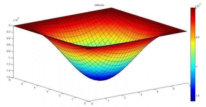
(c) Deflection profile of the plate (MATLAB)
Maximum deflection at mid span = – 0.001593681267073 m
wmax = 1.59368 mm
Comparing this result with other methods;
Classical solution (Timoshenko) = 1.593 mm
Finite element Analysis (Staad Pro) = 1.560 mm (rectangular mesh size division = 25 x 25)
References
[1] Ferreira J.P. (2014): Elasto-plastic analysis of structures using an Isogeometric Formulation. M.Eng thesis presented to the Department of Mechanical Engineering , University of Porto, Portugal
[2] Cottrell J, A. Reali, Y. Bazilevs, and T. Hughes (2006): “Isogeometric analysis of structural vibrations,” Computer Methods in Applied Mechanics and Engineering, vol. 195, no. 41– 43, pp. 5257 – 5296. John H. Argyris Memorial Issue. Part II.
[3] Raknes Siv Bente (2011): Isogeometric Analysis and Degenerated Mappings. An M.Sc thesis submitted to the Department of Mathematical Sciences, Norwegian University of Science and Technology.
[4] Timoshenko S. And S. Woinowsky-Krieger (1959): Theory of plates and shells. McGraw-Hill Book Company, Inc


I admire this article for the well-researched content and excellent wording. I got so involved in this material that I couldn’t stop reading. I am impressed with your work and skill. Thank you so much.
flyer design in chennai
You have shared a nice article here about the Isogeometric Analysis and CAD. Your article is very informative and useful for those who are interested to know more about the Isogeometric Analysis. Thanks for sharing this article here. 3d Modeling Services Ireland