In the construction of steel structures, there is always a need to join steel members for the purpose of continuity. It is not always possible to have the full lengths of members to span the desired length due to production, handling, and transportation issues. As a result, it is very common to bolt or weld two or more steel members, so as to achieve the desired length.
A bolted beam splice connection is a structural joint used in the construction of steel beams. It is designed to connect two or more beams end-to-end to form a longer beam, increasing the span length or overall structural capacity. The design of a bolted beam splice connection involves several considerations to ensure its strength, stability, and reliability.
The design of a bolted beam splice connection involves careful consideration of load transfer, bolted connection details, splice configuration, stiffness requirements, structural analysis, connection detailing, and material properties. By implication, all the anticipated design forces acting at the point of the beam splice must be taken into consideration during the design.
Therefore, the design involves performing structural analysis to determine the forces and moments acting on the connection. This analysis considers the applied loads, beam properties, and connection geometry. Finite element analysis or other advanced analysis methods may be employed to evaluate the connection’s behaviour under different loading conditions.
In this article, we are going to look at a design example of a beam splice connection (beam-to-beam connection using steel plates). This joint should be able to transmit bending, shear, and axial forces.
Design and functions of Bolted Splice Connections
The primary function of a beam splice connection is to transfer the loads between the beams effectively. The connection should be designed to transfer axial forces, shear forces, and bending moments from one beam to another without significant deformation or failure.
The connection typically consists of bolts, washers, and nuts. High-strength bolts are commonly used due to their ability to withstand heavy loads. The number, size, and grade of bolts are determined based on the design requirements and the applied loads.
The configuration of the splice connection depends on the structural requirements and the type of loads being transferred. Common types include full-depth end plate splices, extended end plate splices, and flange plate splices. The choice of splice configuration is influenced by factors such as the beam profile, connection stiffness, and fabrication constraints.
The stiffness of the splice connection plays a crucial role in maintaining the overall structural integrity and load distribution. Adequate stiffness helps to limit deflections and minimize differential movement between the spliced beams. The connection should be designed to ensure that it does not introduce excessive additional stiffness or flexibility to the overall beam system.
Design Example
Let us design a bolted beam splice connection for a UB 533 x 210 x 101 kg/m section, subjected to the following ultimate limit state loads;
MEd = 610 kNm
VEd = 215 kN
NEd = 55 kN
At serviceability limit state;
MEd,ser = 445 kNm
VEd,ser = 157 kN
NEd,ser = 41 kN
Properties of UB 533 x 210 x 101
h = 536.7 mm
b = 210 mm
d = 476.5 mm
tw = 10.8 mm
tf = 17.4 mm
r = 12.7 mm
A = 129 cm2
Iy = 61500 cm4
Iz = 2690 cm4
Wel,y = 2290 cm3
Wpl,y = 2610 cm3;
hw = h – 2tf = 476.5 mm
Cover plates
Let us assume 20 mm thick cover plates for the flanges and 15 mm thick plates for the web. The thickness and dimension to be confirmed later in the post.
Bolts
M24 preloaded class 8.8 bolts
Diameter of bolt shank d = 24mm
Diameter of hole d0 = 26mm
Shear area As = 353 mm2
Materials Strength
Beam and cover plates;
fy,b = fy,wp = 275 N/mm2
fu,b = fu,wp = 410 N/mm2
Bolts
Nominal yield strength fyb = 640 N/mm2
Nominal ultimate strength fub = 800 N/mm2
Partial Factors for Resistance (BS EN 1993-1- NA.2.15)
Structural Steel
γm0 = 1.0
γm1 = 1.0
γm2 = 1.1
Parts in connections
γm2 = 1.25 (bolts, welds, plates in bearing)
γm3 = 1.0 (slip resistance at ULS)
γm3,ser = 1.1 (slip resistance as SLS)
Step 1: Internal Forces at Splice
For a splice in flexural member, the parts subject to shear (the web cover plates) must carry, in addition to the shear force and moment due to the eccentricity of the centroids of the bolt groups on each side, the proportion of moment carried by the web, without any shedding to the flanges.
The second moment of area of the web is;
Iw = [(h – 2tf)3tw/12]
Iw = [(476.53 × 10.8)/12] × 10-4 = 9737 cm4
Therefore the web will carry 9737/61500 = 15.8% of the moment in the beam (assuming an elastic stress distribution), while the flange will carry the remaining 84.2%.
The area of the web is;
Aw = 476.5 × 10.8 × 10-2 = 51.462 cm2
Therefore, the web will carry 51.462/129 = 39.8% of the axial force in the beam, while the flange will carry the remaining 60.1%.
Forces at ULS
The force in each flange due to bending is therefore given by;
Ff,M,Ed = 0.842 × [(MEd)/(h – tf)]
Ff,M,Ed = 0.842 × [(610 × 106)/(536.7 – 17.4)] × 10-3 = 989 kN
And the force in each flange due to axial force is given by;
Ff,N,Ed = 0.601 × (55/2) = 16.53 kN
Therefore
Ftf,Ed = 989 – 16.53 = 972.47 kN
Fbf,Ed = 989 + 16.53 = 1005.53 kN
The moment in the web = 0.158 × 610 = 96.38 kNm
The shear force in the web = 215 kN
The axial force in the web = 0.398 × 55 = 21.89 kN
Forces at SLS
The force in each flange due to bending is therefore given by;
Ff,M,Ed = 0.842 × [(MEd,ser)/(h – tf)]
Ff,M,Ed = 0.842 × [(445 × 106)/(536.7 – 17.4)] × 10-3 = 721.53 kN
And the force in each flange due to axial force is given by;
Ff,N,Ed = 0.601 × (41/2) = 12.3205 kN
Therefore
Ftf,Ed = 721.53 – 12.32 = 709.21 kN
Fbf,Ed = 721.53 + 12.32 = 733.85 kN
The moment in the web = 0.158 × 445 = 70.31 kNm
The shear force in the web = 157 kN
The axial force in the web = 0.398 × 41 = 16.318 kN
Choice of Bolt Number and Configuration
Resistances of Bolts
The shear resistance of bolts at ultimate limit state
For M24 bolts in single shear = 132 kN
For M24 bolts in double shear = 265 kN
Flange Splice
For the flanges, the force of 1005.53 kN at ULS can be provided by 8 M24 bolts in single shear.
The full bearing resistance of an M24 bolt in a 20 mm cover plate (without reduction for spacing and edge distance) is;
Fb,max,Rd = (2.5fudt)/γm2
Fb,max,Rd = [(2.5 × 410 × 24 × 20)/1.25] × 10-3 = 393.6 kN
This is much greater than the resistance of the bolt in single shear, and thus the spacings do not need to be such as to maximise the bearing distance. Four lines of 2 bolts at a convenient spacing may be used.
Web Splice
For the web splice, consider one or two lines of 4 bolts on either side of the centreline. The full bearing resistance on the 10.8 mm web is;
Fb,max,Rd = (2.5fudt)/γm2
Fb,max,Rd = [(2.5 × 410 × 24 × 10.8)/1.25] × 10-3 = 212.54 kN
This is less than the resistance in double shear, and will therefore determine the resistance at ULS. To achieve this value, the spacings will need to be;
e1 ≥ 3d0 = 3 × 26 = 78mm
p1 ≥ 15d0/4 = (15 × 26)/4 = 97.5 mm
e2 ≥ 1.5d0 = 1.5 × 26 = 39 mm
p2 ≥ 3d0 = 3 × 26 = 78mm
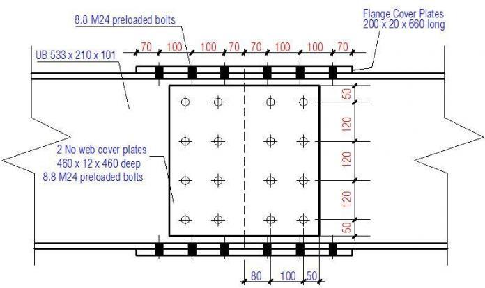
Initially, try 4 bolts at a vertical spacing of 120mm at a distance of 80mm from the centreline of the splice.
The additional moment due to the eccentricity of the bolt group is;
Madd = 215 × 0.08 = 17.2 kNm
Bolt forces at ULS
Force/bolt due to vertical shear = 215/4 = 53.75 kN
Force/bolt due to axial compression = 21.89/4 = 5.47 kN
Force/bolt due to moment (considering top and bottom bolts only) = (96.38 + 17.2)/0.36 = 315.5 kN
Thus, a single row is adequate.
Considering the second line of bolts at a horizontal pitch of 100mm
Force/bolt due to vertical shear = 215/4 = 53.75 kN
Force/bolt due to axial compression = 21.89/4 = 5.47 kN
Force/bolt due to moment (considering top and bottom bolts only) = (96.38 + 17.2)/0.36 = 315.5 kN
The additional moment due to eccentricity of this bolt group is;
Madd = 215 × (0.08 + 0.1/2) = 27.95 kN.m
The polar moment of inertia of the blot group is given by;
Ibolts = 6 × 1202 + 8 × (100/2)2 = 106400 mm2
The horizontal component of the force on each top and bottom bolt is;
FM,horiz = {[(96.38 + 27.95) × 120]/106400} × 103 = 140.22 kN
The vertical component of the force on each top and bottom bolt is;
FM,vert = {[(96.38 + 27.95) × 50]/106400} × 103 = 58.425 kN
Therefore, the resultant force on the most highly loaded bolt is;
Fv,Ed = sqrt[(53.75 + 58.425)2 + (140.22 + 5.47)2] = 183.87 kN
This is less than the full bearing resistance, and is therefore satisfactory for such a bolt spacing.
Chosen Joint Configuration
Summary of cover plate dimensions and bolt spacing
Flange cover plates;
Thickness tfp = 20 mm
Length hfp = 660 mm
Width bfp = 200 mm
End distance e1,fp = 70 mm
Edge distance e2,fp = 30 mm
Spacing
In the direction of the force p1,f = 100 mm
Transverse to direction of force p2,f = 120 mm
Across the joint in direction of force p1,f,j = 120 mm
Web cover plates;
Thickness twp = 12 mm
Length hwp = 460 mm
Width bwp = 460 mm
End distance e1,wp = 50 mm
Edge distance e2,wp = 50 mm
Spacing
Vertically p1,w = 120 mm
Horizontally p2,w = 100 mm
Horizontally across the joint p1,w,j = 160 mm
Resistance of flange splices
Resistance of net section
The resistance of a flange cover plate in tension (Nt,fp,Rd) is the lesser of Npl,Rd and Nu,Rd.
Here;
Nu,Rd = (0.9Anet,tpfu,fp)/γM2
Where;
Anet,fp = (bfp – 2d0)tfp = [200 – (2 × 26)] × 20 = 2960 mm
Therefore;
Nu,Rd = [(0.9 × 2960 × 410 )/1.1] × 10-3 = 992.945 kN
Npl,Rd = (Afpfy,fp)/γM0 = [(200 × 20 × 275)/1.0] × 10-3 = 1100 kN
Since 1100 kN > 992.945 KN
Nt,fp,Rd = 992.945 kN
For the flange in tension;
Ftf,Ed = 989 – 16.53 = 972.47 kN
Therefore, the tension resistance of a flange cover plate is adequate.
Block Tearing Resistance;
n1,fp = 3 and n2,fp = 2;
The resistance to block tearing (Nt,Rd,fp) is given by:
Nt,Rd,fp = {(fu,fpAnt,fp)/γm2} + {[Anv,fp(fy,fp/√3)]/γm0}
Where:
Ant,fp = tfp(2e2,fp – d0)
Ant,fp = 20 × [(2 × 40) – 26] = 1080 mm2
Anv,fp = 2tfp[(n1,fp – 1)p1,fp + e1,fp – (n1,fp – 0.5)d0]
Anv,fp = 2 × 20[(3 – 1) × 100 + 70 – (3 – 0.5) × 26] = 8200 mm2
Therefore;
Nt,fp,Rd = {[(410 × 1080)/1.1] + [(8200 × 265/√3)/1.0]} × 10-3 = 1657.127 kN
Resistance of cover plate to compression flange
Local buckling resistance between the bolts need not be considered if:
p1/t ≤ 9ε
ε = sqrt(235/fy,fp) = sqrt(235/265) = 0.94
9ε = 9 × 0.94 = 8.46
Here, the maximum spacing of bolt across the centreline of the splice p1,f,j = 120 mm
p1,f,j/tfp = 120/20 = 6
Since 8.46 > 6, no local buckling verification required.
RESISTANCE OF WEB SPLICE
Resistance of web cover plate in shear;
The gross shear area is given by:
Vwp,g,Rd = (hwptwpfy,wp/1.27γm0√3)
For two web cover plates;
Vwp,g,Rd = 2{[(460 × 12)/1.27] × [275/√3]} × 10-3 = 1380.185 kN
VEd = 215 kN. Therefore, the shear resistance is adequate.
The net shear area is given by:
Vwp,net,Rd = Av,wp,net(fu,wp/√3)/γm2
Av,net = (hwp – 3d0)twp
= (460 – 3 × 26) × 12 = 4584 mm2
For two web cover plates;
Vn,Rd = {2 × [4584 × (410/√3)]/1.1} × 10-3 = 1972.9 kN
Therefore, shear resistance is adequate.
Resistance to block tearing
Vb,Rd = (fu,wpAnt)/γm2 + (fy,wpAnv.Anv)/γm0√3
For a single vertical line of bolts;
Ant = twp(e2 – d0/2)
Ant = 12 × (50 – 26/2) = 444 mm2
Anv = twp – e1 – (n1 – 0,5)d0)
Anv = 12 × [460 – 50 – (3 – 0.5)26] = 4140 mm2
For two web plates
Vb,Rd = 2 × {[(410 × 460)/1.1] + [(275 × 4140)/(√3 × 1.0)]} × 10-3 = 1657.53 kN
VRd = min{1657.53, 1972.9, 1380.185 }
VRd = 1380.185 kN
VEd/VRd = 215/1380.185 = 0.1557 < 1.0
This is ok.
Resistance of beam web
Resistance of net shear area
Vn,w,Rd = [Av,net(fu/√3)]/γm2
Where;
Av,net = Av – 3d0tw
Av = A – 2btf + (tw + 2r)tf but not less than ηhwtw
Av = 12900 – (2 × 210 × 17.4) + (10.8 + 2 × 12.7) × 17.4 = 6221.88 mm2
Av = 6221.88 – (3 × 26 × 10.8) = 5379.48 mm2
Thus;
Vn,w,Rd = {[5379.48 × (410/√3)]/1.1} × 10-3 = 1157.632 kN
This is ok.
Resistance of web cover plate to combined bending, shear, and axial force
Vwp,Rd = 1380.185 kN
Vsub>Ed = 215 kN < 1380.185 kN
Therefore, the effects of shear can be neglected
Awp = 12 × 460 = 5520 mm2
Modulus of the cover plate = (12 × 4602)/6 = 423200 mm3
Nwp,Rd = 12 × 460 × 275 × 10-3 = 1518 kN
Therefore, for two web cover plates
Mc,wp,Rd = [(2 × 423200 × 275)/1.0] × 10-6 = 232.76 kNm
For two web cover plates;
Npl,Rd = 2 × 1518 = 3036 kN
Mwp,Ed = 96.38 + 27.95 = 124.33 kNm
Nwp,Ed = 21.89 kN
Mwp,Ed/Mc,wp,Rd + Nwp,Ed/Nwp,Rd
124.33/232.76 + (21.89/3036) = 0.541 < 1.0
Therefore, the bending resistance of the web cover plates is adequate.
Thank you for visiting Structville today, and God bless.








• Although each body is still unique, there is a jean for every size. Whether you are petite, long-legged, large and tall, or any other way, blue jeans are made to suit the body you're in. Comfort and ease of wearing are prominent strengths in any size. BIM Consulting in USA
BIM documentation in USA
BIM Implementation in USA
Instructions unclear, M20 bolt