In our last post, we were able to establish how we can load box culverts properly. If you missed the post, kindly follow the link below to read it;
Loading and Analysis of Box Culverts to Eurocode 2
In this post, we are going to describe how we can model, load, and analyse box culverts using Staad Pro software. Here is a quick a recap of the properties of the box culvert under consideration;
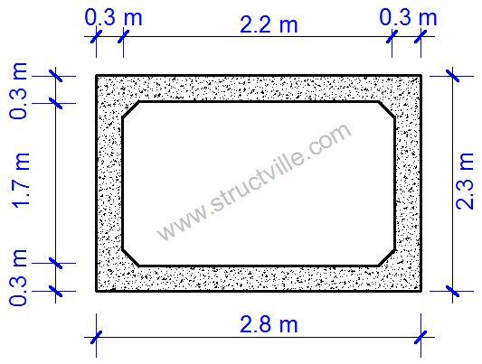 |
| Fig 1: Section of the Box Culvert |
(1) Meshing
Here, the box culvert is idealised with dimensions based on centre to centre of the slabs and walls. This means that the width of the box culvert that will be input into Staad Pro is 2.5 m, while the depth will be 2.0 m. This can be started by forming the nodes in the global XY plane, and then copying and pasting for the length of 8 m in the Z global direction. The output of this operation is as given below;
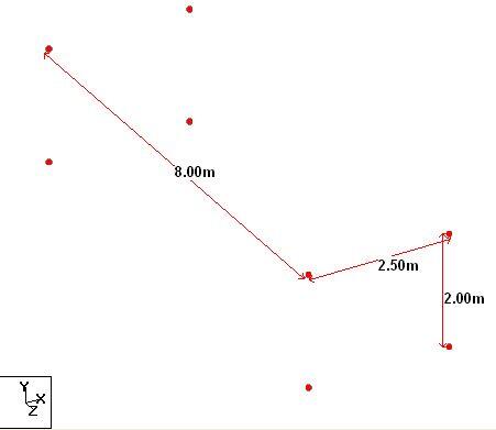 |
| Fig 2: Initial Nodes for Commencement of Modelling |
After forming this, the wing walls can also be formed, which is followed by meshing (rectangular or polygonal) to form the shell of the box culvert. The final output of the meshing operation is as shown below;
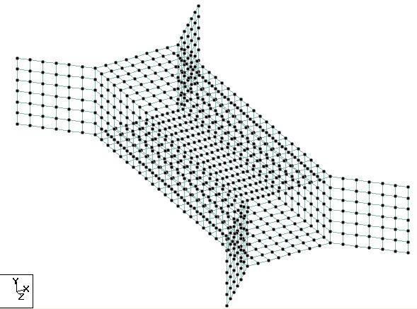 |
| Fig 3: Fully Meshed Box Culvert |
The meshing process can be completed by adding plate thickness of 300 mm to all the elements.
(2) Assigning of support conditions/foundations
This is an important aspect of modelling structures. A purely rigid approach will involve using fixed supports, but note that employing 3D model for this purpose will not be very appropriate, but a simple 2D frame model will be better. There are many proposals on how culverts can be modelled as 2D frames, and the reader is advised to consult as many publications as possible. However, to incorporate the effects of soil-structure interaction (to a limited degree though) on our model, we can employ the use of ‘elastic plate‘ foundation option on our model.
If we assume that the supporting soil and the backfill are of the same material, then we can maintain the same angle of internal friction of 30°. Angle of internal friction of 30° can suggest a loose – medium dense sand in its undisturbed state, therefore we can take a modulus of subgrade reaction of 50,000 kN/m2/m for a well compacted sand. For a slightly compacted sand, you can take a value of 30,000 kN/m2/m.
So we can input this option into Staad Pro using ‘compression only’ option (see the dialog box below in Fig 4);
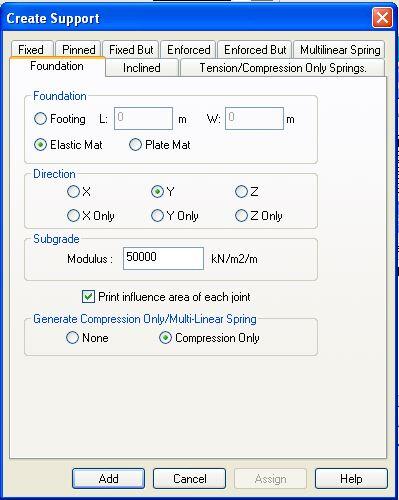 |
| Fig 4: Elastic Mat Foundation Dialog Box |
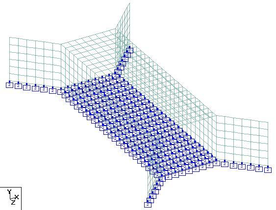
When this is applied on the structure, we have the final model as shown in Fig 5;
 |
| Fig 5: Application of Elastic Mat Foundation on the Model |
What this model (Fig. 5) means is that every node of the base slab is in contact with the soil, and the soil is represented by a spring of stiffness 50,000 kN/m2/m which is the subgrade modulus of the soil.
(3) Loading
This is another important aspect of modelling structures because analysis results would go very wrong if the loads are not applied properly. If you review our previous post, we considered two construction cases;
(A) where the culvert is buried under the soil, and
(B) where is there no earth fill on top of the culvert.
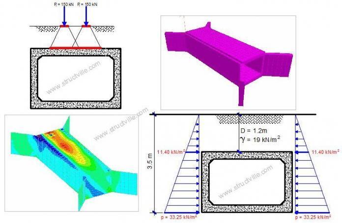
When there is no earth fill on the culvert, the traffic load is directly on the top slab of the culvert as tandem loads and as UDL, but when there is earth fill, traffic load is dispersed in the ratio of 2:1 as UDL on the culvert. We are going to consider 5 load cases in our analysis in this model;
(1) Self weight and other superimposed actions
(2) Vertical earth load
(3) Traffic load
(4) Surcharge load
(5) Horizontal earth pressure load
These load cases are considered independently at first, and then combined with appropriate partial factors of safety to determine the design actions. Please note that effects of ground water and the pressure in the shell of the culvert when it is filled with water is an important load case too but was not considered in this post. We have determined the magnitude of these loads in our previous post, and we are going to apply them on the box culvert for Case A and Case B.
In our previous post, we were able to analyse the loads on the culvert for Case A as follows;
(1) Self weight: To be calculated automatically by Staad + 1.69 kN/m2 (self weight of asphalt wearing course)
NB: In some cases, the partial factor of safety for self weight of concrete elements and other superimposed dead loads like asphalt wearing course might be different, so in that case, it is very advisable to treat each of them as a separate load case on Staad.
(2) Vertical earth load on the culvert = 22.80 kN/m2
(3) Traffic load dispersed as UDL = 59.523 kN/m2
(4) Horizontal surcharge load = 5.0 kN/m2
(5) Horizontal earth pressure load = trapezoidal distribution with minimum earth pressure of 11.40 kN/m2 at the top of the culvert and 33.25 kN/m2 at the bottom of the culvert
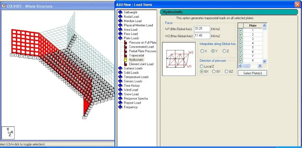 |
| Fig 6: Application of Horizontal Earth Pressure as Hydrostatic Load on Staad |
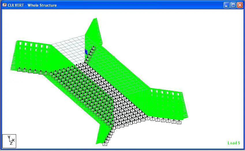 |
| Fig 7: Earth Pressure on the Culvert |
- All permanent actions including superimposed dead load and vertical earth pressure γG = 1.35
- Leading/main traffic action γQ,1 = 1.35
- Traffic surcharge γQ,2 = 1.5
- Horizontal earth pressure and ground water γQ,2 = 1.5
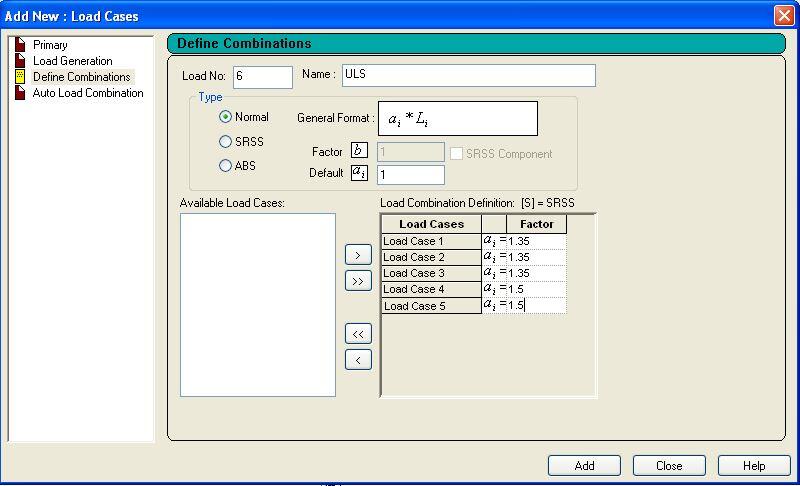 |
| Fig 8: ULS Load Combination Dialog Box |
(4) Analysis
On analysing the structure, we obtain the following results at ultimate limit state;
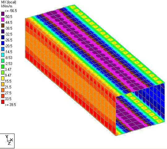 |
| Fig 9: Transverse Bending Moment |
[Get this publication on Design of Residential Buildings Using Staad, Orion, and Manual Calculations into your mailbox by clicking HERE or by clicking on the book cover]
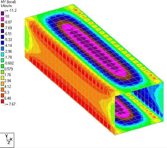 |
| Fig 9: Longitudinal Bending Moment |
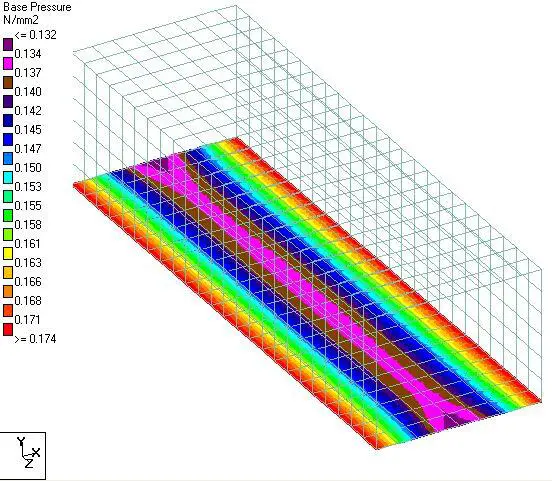 |
| Fig 10: Base Pressure |
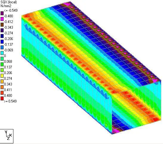 |
| Fig 11: Transverse Shear Stress |
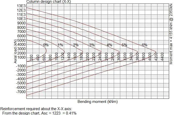
A little consideration will show that the top slab is subjected to an ultimate design moment MEd of 56.5 kNm/m and an axial pull of NEd of 91.5 kN/m (check for membrane stresses in your own Staad Model).
NB: Shear and membrane forces in plates are expressed in Mpa in Staad, so will you have to multiply them with the thickness of the element to get the values in kN/m.
For the top slab of the culvert, the M-N interaction chart is given in Fig. 11 below for obtaining the design reinforcement.
 |
| Fig 12: M-N Interaction Chart on the Box Culvert |
When designed, the area of steel for the axial compression and bending is 1223 mm2/m. Therefore, provision of H16@200 c/c (Asprov = 2010 mm2) on each face will be adequate.
Design Case B: No Earth Fill on Box Culvert
(1) Traffic Loads
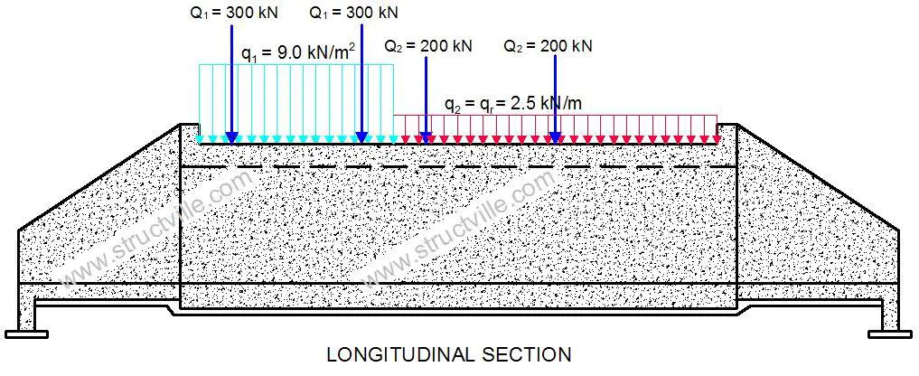
When there is no earth fill on the box culvert, all we have to do is to remove the vertical earth fill load, apply direct traffic load on the top slab, and edit the horizontal earth load from trapezoidal to rectangular. As a reminder, the nature of Load Model 1 (which can be used for global and local verification) on the culvert is given in Fig 14 below;
 |
| Fig 14: Load Model 1 on the Culvert |
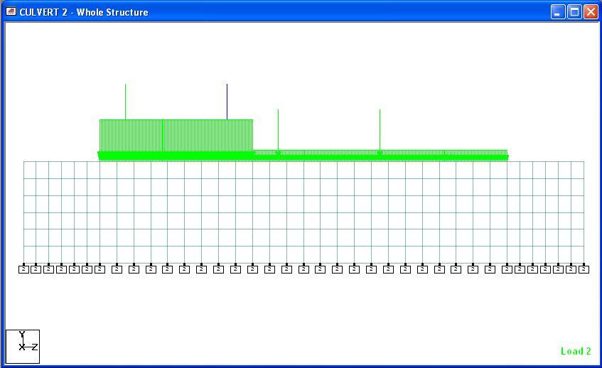
The ideal thing is to apply a moving load on Staad after vehicle definition, such that the worst effect can be obtained. Note that you cannot apply a moving load directly on plate elements on Staad Pro, but you will need to create dummy beam members of negligible stiffness so that the axles can sit on them. In this post, we are not going to bother ourselves with the process, but we are going to treat the wheel load as static.
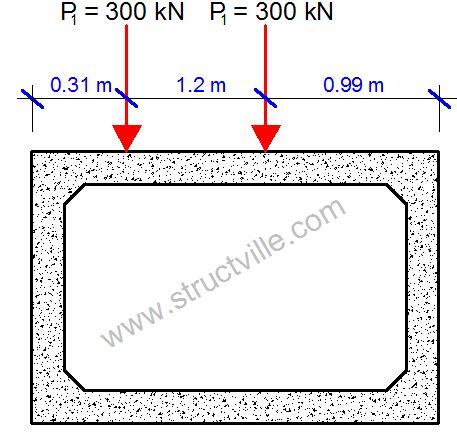
Influence line has shown that the most onerous bending moment is obtained when the front axle is 0.26 m beyond the mid-span of the culvert. Therefore, we are going to apply static wheel load at that location. Remember that it is always recommended to apply the full tandem system of LM1 whenever applicable. The critical location of wheel load on the box culvert for maximum moment is given in Fig 15 below;
 |
| Fig 15: Most Critical Location of Wheel Load on the Culvert |
 |
| Fig 16: Application of LM1 on Staad Pro |
(2) Non-traffic Loads
For Design Case A, it is observed that the self weight of the structure and asphalt layer remains the same, the surcharge load also remains the same, but the horizontal earth pressure changes to triangular distribution with a maximum pressure of 21.85 kN/m2 at the bottom of the culvert.
(3) Analysis
When the structure is analysed, the results at ultimate limit state are as shown below;
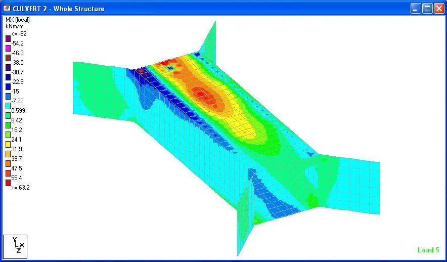 |
| Fig 17: Transverse Bending Moment |
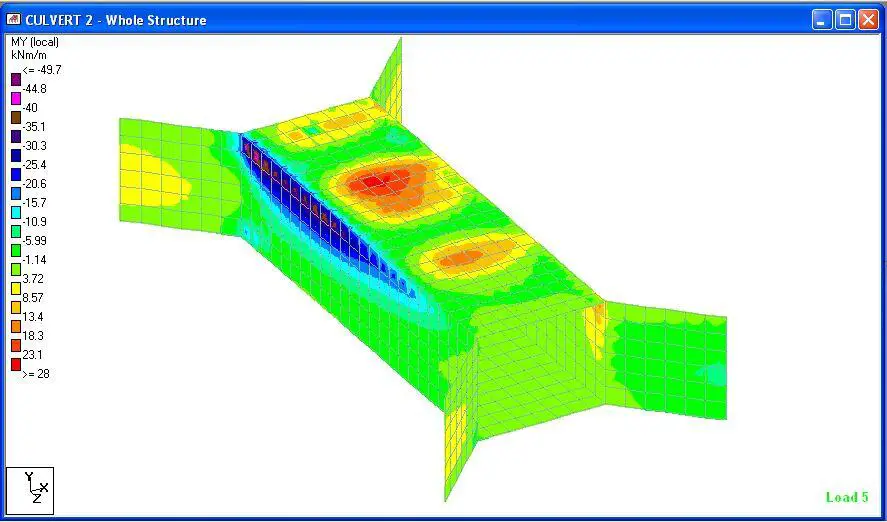 |
| Fig 18: Longitudinal Bending Moment |
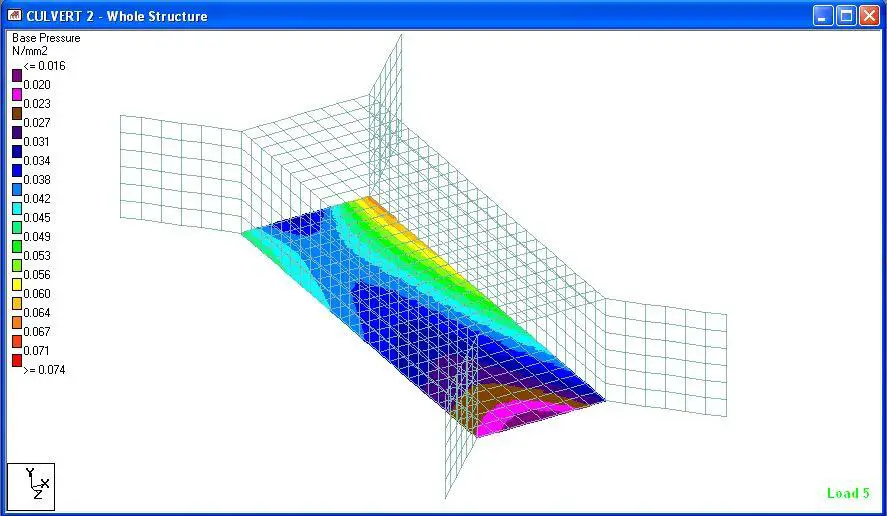 |
| Fig 19: Base Pressure |
Our analysis results have shown that when there is earth fill, the bending moment at ultimate limit state on top of the culvert is about 56.5 kNm/m, but when traffic is directly on top of the culvert, the bending moment is about 62 kNm/m. This is about 8.8% difference.
Thank you for visiting Structville today, and remember to share this post with your friends and colleagues.





Thank you for sharing very informative and creative content.This content is very useful best way to extent the knowledge of 3dsmax classes in indore Revit classes in indore sketchup classes in indore Autocadclasses 3d animation classes in indore photoshop classes in indore vfx classes indore civil design classes indore mechanical institute in indore coreldraw coaching in indore Design centre is the best coaching classes.
Thank you for sharing very informative and creative content.This content is very useful best way to extent the knowledge of Vfx coaching classes in chhindwara graphic design coaching classes in chhindwara autocad coaching classes in chhindwara Fashion design coaching classes in chhindwara 3d animation coaching classes in chhindwara
I am so happy I found your blog and I absolutely love your information about analysis-and design of box culvert using staad pro! I liked and it is wonderful to know about so many things that are useful for all of us! Thanks a lot for this amazing blog!!
Thank you very much sir for sharing this very useful information about box culvert. I hope you can share also up to design of steel reinforcements.
Thank you very much for sharing such knowledge with me.. God Bless..
Kudos to you Engineer for sharing this knowledge of yours in order for others to benefit.
Informative indeed! Thank you so much for sharing your knowledge. This is very helpful.
I kept getting “Section Properties Not Entered For Member” error