A beam and raft foundation is a special type of shallow foundation where ground beams are incorporated into the raft slab along the column lines to enhance the structural performance of the slab and to reduce cost. Therefore, the design of a beam and raft foundation involves the provision of adequate member sizes and reinforcement for the ground beams and slab, while ensuring that the bearing capacity of the soil is not exceeded.
In flat raft slab design, punching shear is a major design requirement that influences the thickness of the slab. This often leads to an excessive thickness of slab members that will be economically detrimental to the owner of the building. However, by introducing ground beams along the column gridlines, the problem of punching shear is eliminated as the column bears on the ground beams. This may lead to the use of thinner slabs and bigger heavily reinforced ground beams.
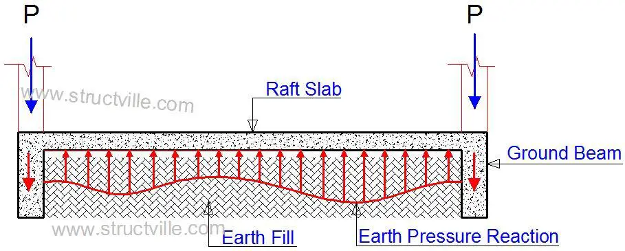
The beams in a beam and raft foundation may be upstand or downstand. The general theory in the design of beam and raft foundations is that the earth pressure intensity as a result of the superstructure load is first resisted by the raft slab, which then transfers the load to the ground beams. Therefore, the uniformly distributed load used in the design of the ground beams is assumed to be transferred from the raft slab.
Since the pressure load on the raft slab is coming from the ground, it follows that the top fibre of the slab is in tension in the sagging areas (span), while the support regions are in tension at the bottom fibre. This is a typical reverse of what is obtainable in the design of suspended solid slabs.
Therefore, for the theory and assumptions made in the design of a beam and raft foundation to be valid, the slab must be in direct contact with the ground, and be stiff enough to resist the earth pressure intensity. This is one of the scepticism of professionals on the use of downstand ground beams in raft foundations.
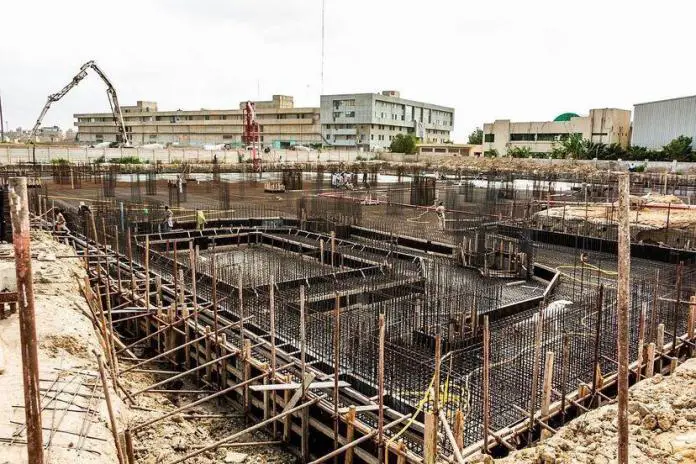
In the case of down-stand beams, the ground beams are constructed into the natural soil, with a height that rises above the natural ground level, in order to make up the architectural level for the ground floor slab. As a result, the foundation must be filled with imported earth material to the ground beam level, before the raft slab concrete is done.
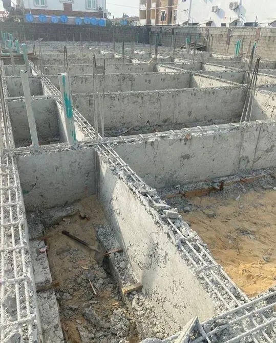
If the imported material is not properly compacted and eventually settles, the raft slab will behave like a suspended slab and the design philosophy will eventually be defeated. Additionally, the foundation slab will bear on a filled ground with unknown bearing capacity. Therefore, the fill material for raft slabs must be high-quality earth materials (preferably granular materials) and must be properly compacted.
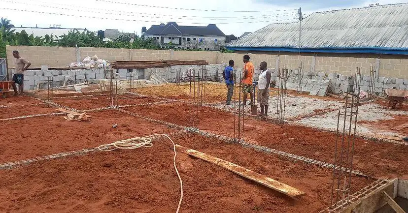
Therefore, upstand ground beams are theoretically more certain since the raft slab bears directly on the natural ground, however, they will be more expensive since another oversite concrete will have to be done. However, down-stand ground beam construction provides an economical advantage to the building owner since the raft slab also functions as the oversite concrete floor.
An Investigation on the Analysis of Beam and Raft Foundation Using Staad Pro
Design Example
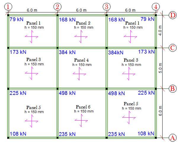
The axial forces in the ground floor columns have been presented below, and have been used to demonstrate how to carry out the design of the beam and raft foundation manually.
Design Data
Allowable bearing capacity of soil = 40 kN/m2
Dimension of all columns = 230 x 230 mm
Dimension of ground floor beams = 1200 x 250 mm
Thickness of ground floor slab = 150 mm
Concrete cover to ground beams = 50 mm (sides and bottom)
Cover to slab = 30 mm
fck = 25 MPa
fyk = 500 MPa
Analysis of the raft slab by rigid approach
A little consideration of Figure 3 will show that the foundation is loaded is symmetrically in the x-direction, therefore we will compute the eccentricity of the load in the z-direction.
Sum of load on gridline D = 79 + 168 + 168 + 79 = 494 kN
Sum of load on gridline C = 173 + 384 + 384 + 173 = 1114 kN
Sum of load on gridline B = 225 + 498 + 498 + 225 = 1446 kN
Sum of load on gridline A = 108 + 235 + 235 + 108 = 686 kN

Resultant of loads R = 686+ 1446 + 1114 + 494 = 3740 kN

Taking moment about the centroid of the base;
M = (-686 x 7.5) – [1446 x (7.5 – 6)] + [1114 x (7.5 – 4)] + (494 x 7.5) = 290 kNm
Eccentricity of the load e = M/R =290/3740 = 0.0775 m to the right hand side
The base dimensions are taken as follows;
L = 6 + 6 + 6 + 0.25 = 18.25 m
B = 6 + 5 + 4 + 0.25 = 15.25m
Pressure distribution Pi = (R/A) ± (6Re/LB2)
On substituting and solving;
Pmax = 13.847 kPa
Pmin = 13.028 kPa
These values are way below the allowable bearing capacity of the soil, therefore there is no need to increase the dimensions of the base. Also, due to the close values of Pmax and Pmin, instead of using a trapezoidal pressure distribution, we can assume a rectangular pressure distribution using the maximum pressure.
Note
Pressure distribution calculation is carried out using SLS load, but we used ULS here. You can convert from ULS to SLS for simple buildings when using Eurocode by using a factor of 1.37 (Ubani, 2017).
Therefore, using a pressure of 13.847 kPa, we can design the raft slabs and the ground beams using the conventional methods which I believe that we are familiar with.
Design of the raft slab
The design of the raft slab is done just like the design of a normal suspended floor, but there is usually no need to check for deflection. For raft foundations without ground beams, punching shear is also very critical.
Self weight of the slab = 25 kN/m2 x 0.15 m = 3.75 kN/m2
Design pressure for the raft slab = 13.85 – 3.75 = 10.1 kN/m2 (note that it will be improper to factor the self-weight of the ground floor slab since it is favourable in this case)
Effective depth of the slab d = h – Cc – ϕ/2 = 150 – 30 – 10/6 = 115 mm
Where Cc = concrete cover of the raft slab, and ϕ is the diameter of the reinforcement to be used.
General Design Formula
k = MEd/(fck bd2 )
z = d[0.5 + √(0.25 – 0.882k)]
As1 = MEd/(0.87fyk z)
Asmin = (0.26fctm bt d)/fyk ≥ 0.13bd/100
Design of Panel 1

k = ly/lx = 6/4 = 1.5
Moment coefficient for two adjacent edges discontinuous
| Short Span | Long Span | |
| Mid-span | 0.059 | 0.034 |
| Continuous edge | 0.078 | 0.045 |
Short Span – Mid span
MEd = 9.5 kN.m
k = 0.028
Since k < 0.167 No compression reinforcement required
z = 0.95d
As1 = 193 mm2/m
ASmin = 153 mm2/m
Check if ASmin < 0.0013 b
d (187.2 mm2/m)
Therefore, provide H10 @ 250 c/c TT (Asprov = 314 mm2/m)
Short Span – Continuous Edge
MEd = 12.6 kNm; Asreq = 254 mm2/m
Therefore, provide H10 @ 250 c/c BB (Asprov = 314 mm2/m)
Long Span – Mid span
MEd = 5.5 kNm; Asreq = 127 mm2/m
Therefore, provide H10 @ 250 c/c NT (Asprov = 314 mm2/m)
Long Span – Continuous Edge
MEd = 7.3 kNm; Asreq = 161 mm2/m
Therefore, provide H10 @ 250 c/c TT (Asprov = 314 mm2/m)
Design of the ground beams
The figure above shows the assumed load distribution from the raft slab to the ground beams. For simplicity of hand calculations, we are going to use the formula for load transfer to the ground beams. This gives unconservative results, especially for shear forces induced in the beam. But can be used for design purposes.
Shorter span = nlx/3
Longer span = nlx/3 [1 – 1/3k2]
For the beam on gridline 2
Slab load from Panel 1 and 2
w1 = w2 = nlx/3 = (10.1 × 4)/3 = 13.467 kN/m
Slab load from Panel 3 and 4
w3 = w4 = nlx/3 = (10.1 × 5)/3 = 16.833 kN/m
Slab load from Panel 5 and 6
w5 = w6 = nlx/3 = (10.1 × 6)/3 = 20.2 kN/m
Total load on the spans
wC-D = 13.467 + 13.467 = 26.93 kN/m
wB-C = 16.833 + 16.833 = 33.67 kN/m
wA-B = 20.2 + 20.2 = 40.4 kN/m
The self-weight of the beam in this case is beneficial (favourable), and can be ignored.
We can therefore analyse the ground beam as a continuous beam as follows;

We know that MA = MD = 0 since we are treating it as a simple support.
Let us use the stiffness method for the analysis of the structure. The adopted basic system is shown below.

The canonical equation for the beam is given below;
K11Z1 + K12Z2 + k1P = 0
K21Z1 + K22Z2 + k2P = 0
Analysis of Case 1
Z1 = 1.0; Z2 = 0

K11 = 3EI/6 + 4EI/5 = 1.3EI
K21 = 2EI/5 = 0.4EI
Analysis of Case 2
Z1 = 0; Z2 = 1.0

K21 = 2EI/5 = 0.4EI
K12 = 4EI/5 + 3EI/4 = 1.55EI
K1P = FBA + FBC
FBA = +ql2/8 = (40.5 × 62)/8 = 182.25 kNm
FBC = -ql2/12 = (-33.67 × 5^2)/12 = -70.145 kNm
Hence, K1P = 182.25 – 70.145 = 112.105 kNm
K2P = FCB + FCD
FCB = +ql2/12 = (33.67 × 52)/12 = 70.145 kNm
FCD = -ql2)/8 = (26.93 × 42)/8 = -53.86 kNm
K2P = 70.145 – 53.86 = 16.285 kNm
Therefore;
1.3Z1 + 0.4Z2 + 112.105 = 0
0.4Z1 + 1.55Z2 + 16.285 = 0
On solving;
Z1 = (- 90.161)/EI radians
Z2 = 12.761/EI radians
To determine the support moments;
Mi = Mf + M1Z1 + M2Z2
At support B
MBL = 182.25 – [90.161/EI× 3EI/6] = 137.17 kNm
MBR = -70.145 – [90.161/EI× 4EI/5] + [12.761/EI× 2EI/5]= -137.17 kNm
At support C
MCL= +70.145 – [90.161/EI× 2EI/5] + [12.761/EI× 4EI/5]= 44.289 kNm
MCR = -53.86 + [12.761/EI× 3EI/4] = -44.289 kNm
Using the principles of statics, the span moments and shear force diagrams can be drawn.


Structural Design
Span A – B
MEd = 120.2 kNm
h = 1200 mm
Effective depth d = 1200 – 50 – 10 – (16/2) = 1132 mm (assuming ϕ16 mm reinforcement will be used for the main bars, and ϕ10mm for the links).
Beam width (bw) = 250 mm
k = MEd/(fckbd2) = (120.12 × 10⁶)/(25 × 250 × 11322) = 0.0149
Since k < 0.167 No compression reinforcement required
z = d[0.5 + √(0.25 – 0.882k)] = d[0.5 + √(0.25 – 0.882(0.0149)] = 0.95d
As1 = MEd/(0.87fyk z) = (120.12 × 10⁶)/(0.87 × 500 × 0.95 × 1132) = 257 mm2
To calculate the minimum area of steel required;
fctm = 0.3 × fck2⁄3 = 0.3 × 252⁄3 = 2.5649 N/mm2 (Table 3.1 EC2)
ASmin = 0.26 × fctm/fyk × bt × d
Where bt is the width of the beam in tension. A little consideration will show that the flange of the beam is in tension. If we are to use the flange of the beam the way it is in tension,
ASmin = 0.26 × 2.5649/500 x 2290 x 1132 = 3457 mm2
In BS 8110-1:1997, the minimum area of steel required when the flange is in tension is;
Asmin = (0.26bwh)/100 = (0.26 ×250 ×1200)/100 = 780 mm2
Eurocode experts have suggested using the area of the T-section for the calculation of the minimum reinforcement
Such that the ASmin = 0.26 × fctm/fyk × Ac
Ac = (2290 x 150) + (1050 x 250) = 60600 mm2
ASmin = 0.26 × 2.5649/500 x 60600 = 819 mm2 (this is acceptable).
Therefore provide 5H16 Top (Asprov = 1005 mm2)
Design of support B
MEd = 137.71 kNm
Note that at support B, the web is in tension and we will need to consider the flange width in the calculation of the area of steel required.
l0 = 0.15 (l1 + l2) = 0.15(6000 + 6000) = 1800 mm
b1 = b2 = (6000 – 250)/2 = 2875 mm
l0 = 0.85l1 = 0.85 x 6000 = 5100 mm
beff,1 = beff,2 = (0.2 x 2875) + (0.1 x 1800) = 755 mm which is not less than 0.2l0 = (0.2 x 1800) = 360 mm
Hence, beff,1 = beff,2 = 360 mm < 755 mm
beff = 250 + 360+ 360 = 970 mm
k = MEd/(fck bd2 ) = (137.71 × 10⁶)/(25 × 970 × 11322) = 0.00443
Since k < 0.167 No compression reinforcement is required
z = 0.95d
As1 = MEd/(0.87fyk z) = (137.71 × 10⁶)/(0.87 × 500 × 0.95 × 1132) = 294 mm2
ASmin = 0.26 × 2.5649/500 x 250 x 1132 = 377 mm2
Check = 0.13bd/100 = (0.13 × 250 ×1132)/100 = 367.9 mm2
Therefore provide 2H16 Bottom (Asprov = 402 mm2)
On looking at the internal stresses diagram, this reinforcement provided can go all the way in the beam.
Shear Design
Using the maximum shear force for all the spans
Support B; VEd = 144.46 kN
VRd,c = [CRd,c.k. (100ρ1 fck )1/3 + k1.σcp]bw.d ≥ (Vmin + k1.σcp) bw.d
CRd,c = 0.18/γc = 0.18/1.5 = 0.12
k = 1 +√(200/d) = 1 +√(200/1132) = 1.42 > 2.0, therefore, k = 1.42
Vmin = 0.035k(3/2) fck(1/2) = 0.035 × (1.42)(3/2) × (25)(1/2) = 0.296 N/mm2
ρ_1 = As/bd = 402/(250 × 1132) = 0.00142 < 0.02;
σcp = NEd/Ac < 0.2fcd (Where NEd is the axial force at the section, Ac = cross-sectional area of the concrete), fcd = design compressive strength of the concrete.) Take NEd = 0
VRd,c = [0.12 × 1.42(100 × 0.00142 × 25 )1/3] 250 x 1132 = 73564 N = 73.564 kN
Since VRd,c (73.564 kN) < VEd (144.46 kN), shear reinforcement is required.
The compression capacity of the compression strut (VRd,max) assuming θ = 21.8° (cot θ = 2.5)
VRd,max = (bw.z.v1.fcd)/cotθ + tanθ
V1 = 0.6(1 – fck/250) = 0.6(1 – 25/250) = 0.54
fcd = (αcc fck)/γc = (0.85 × 25)/1.5 = 14.167 N/mm2
Let z = 0.9d
VRd,max = [(250 × 0.9 × 1132 × 0.54 × 14.167)/(2.5 + 0.4)]× 10-3 = 671.896 kN
Since VRd,c < VEd < VRd,max
Hence Asw/S = VEd/(0.87fykzcot θ) = (144.46 × 10³)/(0.87 × 500 × 0.9 × 1132 × 2.5 ) = 0.13
Minimum shear reinforcement;
Asw/S = ρw,min × bw × sinα (α = 90° for vertical links)
ρw,min = (0.08 × √fck)/fyk = (0.08 × √25)/500 = 0.0008
Asw/Smin = 0.0008 x 250 x 1.0 = 0.2
Since 0.200 > 0.13, adopt 0.2 as the minimum shear reinforcement
Maximum spacing of shear links = 0.75d = 0.75 × 1132 = 849
Provide Y8mm @ 300mm c/c as shear links (Asw/S = 0.335) Ok
Download the full calculation sheet from the link below;
Manual Design of Beam and Raft Foundation to Eurocode 2 [PDF]
References
Ubani O.U. (2017): Practical Structural Analysis and Design of Residential Buildings Using Staad Pro V8i, CSC Orion, and Manual Calculations. Ist Edition, Volume 1. Structville Integrated Services
To download the above-named textbook, click on the image below;





Hello, I have browsed most of your posts. This post is probably where I got the most useful information for my research. Thanks for posting, maybe we can see more on this. Are you aware of any other websites on this subject.
Thanks for this piece
Is there an assumption that columns connected to raft foundations don't transmit moments or they are modelled as pinned to the base
Definitely they will transmit moment relative to the stiffness of the connection. But the moment is essentially the column moment. So when designing the ground beams, the reinforcement provided for the beam bending moment caters for the moment transferred from beam-column interaction and vice versa.
Thanks !
Thanks Sir for your analysis and design of ground beam and slab raft for framed structure but how can design this using staad pro.
do i need to pay to receive the full manual analysis for raft foundation,i would also apreciate amanual example on a circular internal rcc ramp and rcc lift shear wall,would gradly pay for the sameespecially with a building with a basement floor
How can your design of beam flat slab be modified when the stiffened raft is cast on swelling/shrinking soils. Can you please send design calculations for same? Thanks in advance
Thanks. I really appreciate this.