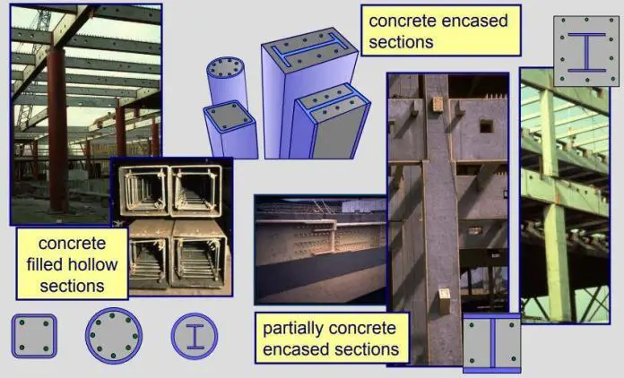
Composite sections of concrete and steel have a lot of advantages, especially in the structural performance and fire resistance of a building. For columns and other compression members, they usually appear as steel-reinforced concrete columns (SRC) or as concrete-filled steel tubes. In this article, we are going to consider the structural design of concrete encased H-section subjected to concentric axial load using Eurocode 4 and BS 5950.
According to BS 5950, the steps to design composite steel columns are as follows;
- Determine ultimate axial load Fc.
- Select trial section and check if it is non-slender.
- Determine rx, ry and Ag from steel tables.
- Determine effective lengths, LEX and LEY
- Calculate slenderness ratios, λEX (= LEX/rx) and λEY (= LEX/ry).
- Select suitable strut curves from Table
- Determine compressive strength, pc
- Calculate compression resistance of member, Pc = Agpc.
- Check Fc ≤ Pc . If unsatisfactory return to 2.
According to Eurocode 4, the simplified steps to design encased steel columns subjected to axial load are as follows;
- Determine the ultimate axial load on the column NEd
- Select a trial section and determine its properties
- Obtain the buckling length of the column L
- Obtain the effective flexural stiffness (EI)eff of the composite section
- Calculate the plastic resistance to compression of the composite section Npl,Rk
- Calculate the relative slenderness of the section (λ) using Euler’s critical load
- Choose the appropriate buckling curve and calculate the corresponding reduction factor χ
- Multiply the plastic resistance to compression with the reduction factor to obtain the buckling resistance of the section Nb,Rd
- Check if NEd < Nb,Rd else return to step 2.
Solved Example
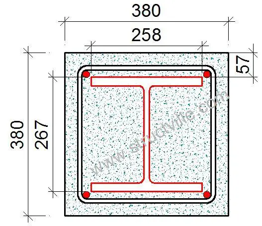
Verify the capacity of UC 254 x 254 x 107 in grade S275 steel encased in a concrete section of 380 x 380 mm to resist a characteristic permanent axial force of 1900 kN and variable axial force of 800 kN using concrete grade C25/30. Column is 3m long and considered pinned at both ends (Area of reinforcement provided = 4H16 (804 mm2 , fyk = 500 N/ mm2).
Solution by BS 5950
The ultimate axial load on the column is given by;
Fc = 1.4Gk + 1.6Qk = 1.4(1900) + 1.6(800) = 3940 kN
Properties of the UC section from Blue Book
Area of UC section (Ag) = 13600 mm2
Radius of gyration (rx) = 113 mm
Radius of gyration (ry) = 65.9 mm
Design strength (py) = 265 N/mm2 (since thickness of flange T = 20.5 mm)
Effective length (LE) = 3.0 m
Effective length
Check that the effective length of column (L = 3000 mm) does not exceed the least of:
(i) 40bc = 40 × 380 = 15200 mm
(ii) 100bc2/dc = (100 × 3802)/380 = 38000 mm
(iii) 250ry = 250 × 65.9 = 16475 mm OK
Radii of gyration for the cased section
For the cased section rx is the same as for UC section = 113 mm
For the cased section ry = 0.2bc = 0.2 × 380 = 76 mm but not greater than 0.2(B + 150) = 0.2(258.8 + 150) = 81.76 mm and not less than that for the uncased section (= 65.9 mm)
Hence ry = 76 mm and rx = 113 mm
Slenderness ratio
λEX = LEX/rx = (3000/113) = 26.548
λEY = LEY/ry = (3000/76) = 39.47
Compressive strength
The relevant compressive strength values for buckling about the x–x axis are obtained from Table 24(b)
of BS 5950 and from Table 24(c) of BS 5950 for bending about the y–y axis.
For λEX = 26.548 and py = 265 N/mm2, pc = 256.45 N/mm2
For λEY = 39.47 and py = 265 N/mm2, pc = 230.848 N/mm2
The compression resistance of the column is therefore given by;
Pc = (Ag + 0.45fcuAc/py)pc
Where:
Ag = 13600 mm2
fcu = 30 N/mm2
Ac = bcdc = 380 x 380 = 144400 mm2
pc = 265 N/mm2
pc = 230.848 N/mm2
Pc = [13600 + (0.45 x 30 x 144400)/265] x 230.848 x 10-3 = 4837.703 kN
Check that Pc is not greater than the short strut capacity, Pcs , given by;
Pcs = (Ag + 0.25fcuAc /py)py = [13600 + (0.25 x 30 x 144400)/265] x 265 x 10-3 = 4687 kN (this is less than Pc , therefore, take Pcs)
Fc /Pc = 3940 /4687 = 0.840 < 1.0 Okay
Design by Eurocode 4
At ultimate limit state;
NEd = 1.35Gk + 1.5Qk = 1.35(1900) + 1.5(800) = 3765 kN
Effective length of the column L = 3000 mm
Area of UC section (Aa) = 13600 mm2
Radius of gyration (iy) = 113 mm
Radius of gyration (iz) = 65.9 mm
Design strength (fy) = 265 N/mm2 (since thickness of flange T = 20.5 mm)
Iy = 17500 cm4
Iz = 5930 cm4
E = 210000 N/mm2
The plastic resistance to compression Npl,Rk = Aa.fy + 0.85Acfck + Asfyk
Aa = 13600 mm2
fy = 265 N/mm2
Ac = 380 x 380= 144400 mm2
fck = 25 N/mm2
As = 804 mm2
fyk = 500 N/mm2
Npl,Rk = [(13600 x 265) + (0.85 x 144400 x 25) + (804 x 500)] x 10-3 = 7074.5 kN
The relative slenderness λi = ( Npl,Rk / Ncr )0.5
Ncr,i = π2(EI)eff,i /L2
(EI)eff,i = EaIa + 0.6EcmIc + EsIs
Ea = Es = Elastic modulus of the structural steel and reinforcement respectively = 210000 N/mm2
Ia = Moment of inertia of structural steel in the relevant axis
Ecm = Modulus of elasticity of concrete = 22(fck/10)0.3 (GPa) = 28960 N/mm2 (see Table 3.1 of Eurocode 2)
Ic = moment of inertia of the uncracked concrete section = bd3/12 = (380 x 3803)/12 = 17376.133 x 105 mm4
Is = moment of inertia of the reinforcement = πD4/64 = (π x 164)/64 = 3216.99 mm4 (for four bars = 4 x 3216.99) = 12867.96 mm4
Hence;
(EI)eff,y = (210000 x 17500 x 104) + (0.6 x 28960 x 17376.133 x 105) + (210000 x 12876.96) = 6.69455 x 10¹³ N.mm2
(EI)eff,z = (210000 x 5930 x 104) + (0.6 x 28960 x 17376.133 x 105) + (210000 x 12876.96) = 4.26485 x 10¹³ N.mm2
Ncr,y = [(π2 x 6.69455 x 1013) /30002] x 10-3 = 73413.955 kN
Ncr,z = [(π2 x 4.26485 x 1013)/30002] x 10-3 = 46769.313 kN
λy = (Npl,Rk / Ncr,y)0.5 = (7074.5/73413.955)0.5 = 0.310
λz = (Npl,Rk / Ncr,z)0.5 = (7074.5/46769.313)0.5 = 0.389
Check h/b ratio = 266.7/258.8 = 1.0305 < 1.2, and tf < 100 mm (Table 6.2 EN 1993-1-1:2005)
Therefore buckling curve b is appropriate for y-y axis, and buckling curve c for z-z axis. The imperfection factor for buckling curve b α = 0.34 and curve c = 0.49 (Table 6.1)
Φ = 0.5 [1 + α(λ – 0.2) + λ2]
Φy = 0.5 [1 + 0.34 (0.310 – 0.2) + 0.3102] = 0.567
Φz = 0.5 [1 + 0.49 (0.389 – 0.2) + 0.3892 ] = 0.622
X = 1/[Φ + √(Φ2 – λ2)]
Xy = 1/[0.567 + √(0.5672 – 0.3102)] = 0.959
Xz = 1/( 0.622 + √(0.6222 – 0.3892)) = 0.903
Therefore Nb,Rd = (Xz Npl,Rk)= (0.903 x 7074.5) = 6388.685 kN
NEd /Nb,Rd = 3765/6388.685 = 0.589 < 1.0 kN Okay

