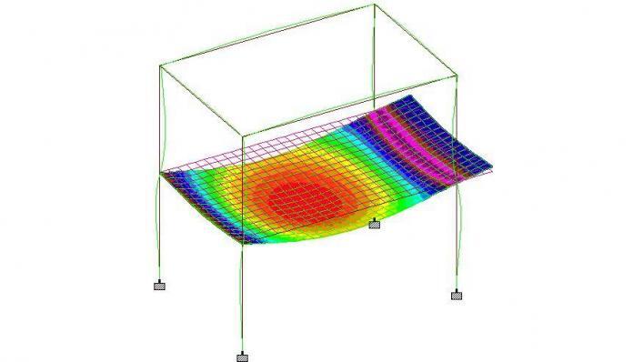
Deflection is one of the most important serviceability limit state criteria in the design of reinforced concrete structures. Excessive deflection in a structure can lead to cracking of finishes, impaired functionality, and unsightly appearance. Different codes of practice have provisions for controlling deflection in concrete structures. In BS 8110-1:1997 and EN 1992-1-1 (Eurocode 2), deflection can be assessed using the simplified span/depth ratio (deemed-to-satisfy rules) or by following the rigorous method (direct calculation of deflection). However, rigorous method is lengthy and has numerous uncertainties involved in the calculation, hence the span/depth ratio approach is widely used. In both codes of practice, compression reinforcement has been shown to be beneficial to the deflection response of reinforced concrete structures.
Concrete is good in compression but weak in tension. As a result, steel reinforcement is usually provided in the tension zone of concrete structures to resist tensile stresses. Sometimes, steel is provided in the compression zone to assist concrete in resisting compression, and in this case, is normally referred to as doubly reinforced section. The major reasons for providing compression reinforcement in concrete structures are;
- to reduce long-term deflection due to sustained loading,
- to increase ductility,
- to changing failure mode from compression-initiated to tension-initiated, and for
- ease in construction (for example using hanger bars to provide support for stirrups).
However, it has been recognised that deflection in a concrete beam and slab increases with time for up to nine years[1]. The long-term deflection of a reinforced concrete member under sustained load is mainly due to creep and shrinkage, and it is usually larger than the immediate deflection[2]. It is important to realise that creep and shrinkage are time-dependent properties of concrete, which are influenced by environmental conditions and the concrete mix design[3]. While creep depends on the sustained load, shrinkage is independent of the load. Other important concrete properties used in assessing level of deflection are the modulus of elasticity, modulus of rupture, and tensile strength properties.
In normal strength concrete, compression reinforcement helps in reducing creep under sustained load in the compression zone, and this helps in reducing the final deflection of the structure. However, research has suggested that the effect of compression reinforcement may be minimal in reducing deflection in high strength concrete structures due to low creep[4]. Studies have shown that the effect of compression reinforcement in reducing long term deflection is dependent on the compressive strength of the concrete[4]. However, compression reinforcement is rarely used for the purpose of resisting deflection in concrete structures.
When the props and formwork are removed from the soffit of a slab, it undergoes immediate elastic deflection if the load is low. If the load is high, there will be cracks in the tension zone (say mid-span), and the deflection may not be entirely elastic[1]. However in the long term, the initial deflection under sustained load will increase because of shrinkage, creep, and increased cracking (note that cracking is deemed normal in concrete members).
Concrete drying shrinkage will cause warping of the slab in zones where there are unequal areas of top and bottom reinforcement. This is typical in the mid-span of a reinforced concrete slab, hence the slab will warp downwards and adds to the long-term deflection. The magnitude of warping is found to be directly proportional to the drying shrinkage of the concrete. It continues at a decreasing rate with increasing time for several years after pouring, and is independent of load. Therefore, provision of top reinforcements can curtail the effect of warping, thereby reducing the final deflection.
Read Also…
Structural Design of Cantilever Slabs
Calculation of crack width and crack spacing in reinforced concrete
Furthermore, it is important to note that the actual long-term deflection of a normally reinforced slab or beam in the typical floor of a multi-level building depends on some other factors which may not be duly paid attention to during design. Some of these factors are materials supply, construction techniques, loading history, weather and time. Loading history and method of construction is known to affect the deflection of slabs. The construction load coming from the floor above have been shown to significantly influence the deflection behaviour of slabs in a multi-story building construction[5].
Assessment of deflection in BS 8110
BS 8110-2:1985 says that the sag in a concrete member will become noticeable if the deflection exceeds span/250. According to clause 3.4.6.1 of BS 8110, deflections in a structure may be calculated and then compared with the serviceability requirements given in BS 8110-2:1985. However, in all normal cases the deflections of a beam will not be excessive if the ratio of its span to its effective depth is not greater than the appropriate ratio. The basic span to effective depth ratio is given in Table 3.9 of BS 8110-1:1997 with values of 7 (cantilever), 20 (simply supported), and 26 (continuous members). The basic span/effective depth ratio should be multiplied by modification factors given in in Tables 3.10 and 3.11 of the code. BS 8110-1:1997 acknowledges that compression reinforcement influences deflection.
The modification factor for tension reinforcement of reinforced concrete is given in Table 3.10 of BS 8110-1;
Modification factor = 0.55 + {(477 – fs)/[120(0.9 + M/bd2)]} ≤ 2.0
Where fs is the service stress in the member and it is given by;
fs = 2fyAsreq/3Asprov
Where;
Asprov = Area of steel provided
Asreq = Areas of steel required
fy = yield strength of reinforcement
M = Applied bending moment at ultimate limit state
The modification factor for compression reinforcement is given in Table 3.11 of BS 8110-1 as;
Modification factor for compression reinforcement = (1 + 100As’prov/bd)/(3 + 100As’prov/bd)
Where As’prov is the area of compression steel provided.
In BS 8110-1, the area of compression reinforcement used for the calculation may include all bars in the compression zone, even those not
effectively tied with links.
Read Also…
Formulas for calculating different properties of concrete to Eurocode 2
Structural design of flat slab to Eurocode 2
Assessment of deflection in Eurocode 2
Clause 7.4.1(4) of EC2 says that the utility and appearance of a structure may be impaired when the deflection exceeds span/250. This limit accounts for both long term and short term deflection. Eurocode 2 follows a slightly different approach in assessing the deflection of a reinforced concrete member using the span/depth ratio approach.
EC 2 allows span/effective depth limits (L/d) to be calculated from equations 7.16a, 7.16b and 7.17 of the code:
L/d = K[11+(1.5√fck x ρ0/ρ) + 3.2√fck(ρ0/ρ – 1)1.5] if ρ0 ≤ ρ (7.16a)
L/d = K(11+(1.5√fck x ρ0/(ρ – ρ’)) + √fck √(ρ0‘/ρ))/12) if ρ0 > ρ (7.16b)
where K is a factor which depends on the static system of the structure (structural form). It has a value of 1.0 for simply supported structures, 1.5 for continuous structures, 1.3 for continuous – end span structures, 1.2 for flat slab, and 0.4 for cantilevers.
ρ0 = reference reinforcement ratio = 10-3√fck
ρ = required tension reinforcement ratio
ρ’ = required compression reinforcement ratio
fck = concrete cylinder strength (N/mm²)
Equations 7.16 above have been derived on the assumption that the steel stress at SLS at a cracked section at the midspan of a beam or slab or at the support of a cantilever is 310 MPa (corresponding roughly to fyk = 500 MPa). Where other stress levels are used, the values obtained using Expression (7.16) should be multiplied by 310/σs. It will normally be conservative to assume that:
310/σs = 500/(fyk Asreq/Asprov) (7.17)
Where;
σs = tensile stress at mid-span (support for cantilevers) under the design load at SLS
Asprov = area of steel provided at the section
Asreq = area of steel required at the section for ultimate limit state.
A little observation of equation 7.16 will show that the direct value of compression reinforcement provided cannot be used in EC2 unless the reference reinforcement ratio of 10-3√fck is greater than the actual reinforcement ratio. This goes on to say that the value to be used should be based on the area of compression steel required and not the area of compression steel provided (say H12 mm hanger bars). This is where BS 8110 greatly differs from EC2.
In BS 8110, the area of steel provided can be increased to order to reduce the service stress in the reinforcement. This usually increases the modification factor and the allowable L/d value. However, some questions have been asked on the area of reinforcement to be used in Eurocode assessment of deflection such as that from Beal[6];
It is not clear how Eq. 7.16(a) and (b) are intended to be applied when the reinforcement service stress varies from 310N/mm² as it is not clear how the reinforcement ratio ρ in eq. 7.16 is to be calculated. Is it the actual amount of reinforcement present, or is it the reinforcement which would have been required for a design stress of 310N/mm²? As currently drafted, it is not clear which of these interpretations is correct.
References
[1] Taylor J. P. (2009): The deflection of reinforced concrete. Taylor Lauder Bersten Pty Ltd
[2] Zhon W., Kokai T. (2010): Deflection calculation and control for reinforced concrete flexural members. Canadian Journal of Civil Engineering 37(1):131-134 https://doi.org/10.1139/L09-121
[3] Elaghoury Z. (2019): Long-term deflection of reinforced concrete beams. M.Sc thesis Submitted to the Department of Civil and Environmental Engineering, The University of Western Ontario
[4] Muhaisin M.H., Jawdhari A.R., Ammash H.K. (2019): Revised formula for predicting the long-term deflection ultiplier of normal and high strength concrete. Rev. IBRACON Estruct. Mater. 12(6):1345-1352 http://dx.doi.org/10.1590/s1983-41952019000600007
[5] Vollum R. L. (2009): Comparison of deflection calculations and span-to-depth ratios in BS 8110 and Eurocode 2. Magazine of Concrete Research 61(6):465-476 https://doi.org/10.1680/macr.2009.61.6.465
[6] Beal A. N. (2009): Eurocode 2: Span/depth ratios for RC slabs and beams. The Structural Engineer, Vol. 87 No. 20, 20th October 2009


