Piles are the most preferred type of foundation for supporting the piers of overhead bridges. They offer greater resistance to vertical and horizontal actions from the bridge deck than shallow foundations. Furthermore, they extend the foundation of piers beyond scouring zones so that there will be no loss of bearing capacity. In this article, we are going to show how to design the foundation of a bridge pier using piles.
We have previously talked about the design the piers and pier cap of an overhead bridge. If you missed the post, read it below.
Structural Design of Pier and Pier Caps of Highway Bridges
Let us go ahead and design the foundation of the bridge pier using the soil investigation report shown below.
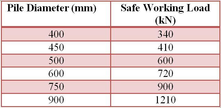
Step 1: Determine the load from the superstructure
The loading on the pier cap at ultimate limit state and serviceability limit state are shown below;
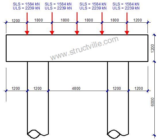
When analysed on Staad Pro, the following support reactions were obtained;
ULS
Vertical support reaction on each pier = 6001.483 kN
Horizontal reaction = 368.443 kN
Bending Moment = 702.032 kNm
SLS
Vertical support reaction on each pier = 4259.247 kN
Horizontal reaction = 260.901 kN
Bending Moment = 497.125 kNm
Step 2: Determination of the number of piles required and the layout
We normally use the service loads to determine the number of piles required for the structure, and use ultimate loads (factored loads) for the structural design.
Using 900 diameter piles, Number of piles required per pier = 4259.247/1210 = 3.52
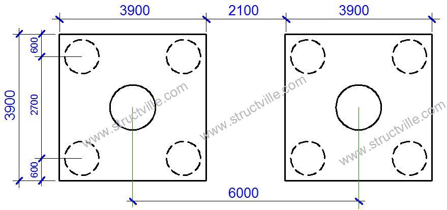
Therefore, provide 4 Piles per pier leg. The layout of the pile cap is shown below. However, attempts were made to combine the two piers under one pile cap, but no economical solution was reached due to the wide spacing of the piers (6 m).
Step 3: Provide longitudinal reinforcement for the piles
The reinforcements required for the piles is usually based on the minimum required for the selected pile diameter
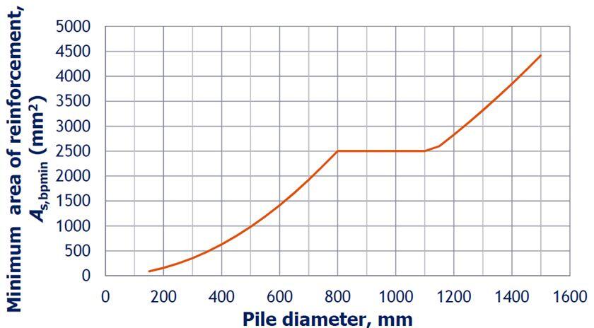
For a pile diameter of 900 mm, the minimum area of steel required is 2500 mm2
Therefore provide 9H20 mm (Asprov = 2826 mm2)
Provide helical links of H10@250 pitch
Read also…
Reinforcement design of piles
Step 4: Analyse and design the pile cap
The required thickness of the pile cap is usually estimated from the diameter of the piles.
h = 2 x diameter of piles + 100 = 2(900) + 100 = 1900 mm deep pile cap
Different approaches can be used for analysing the pile cap such as bending theory, strut and tie method, or finite element analysis. Let us obtain the internal forces in the pile cap from finite element analysis using Staad Pro.
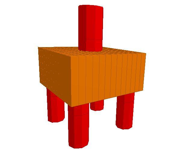
When analysed at ULS, the maximum moment in the pile cap is shown below;
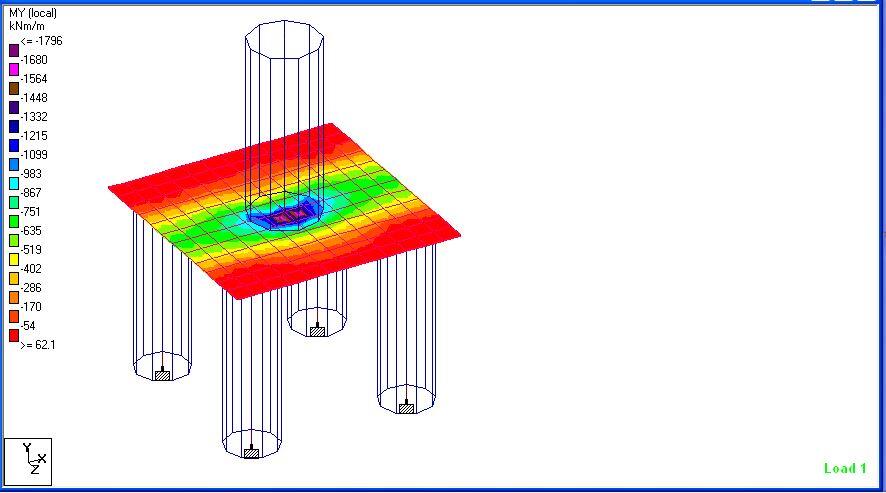
MEd = 1796 KN.m/m
Effective depth d = 1900 – 100 = 1800 mm
k = MEd/(fckbd2) = (1796 × 106)/(40× 1000 × 18002) = 0.0138
Since k < 0.167, no compression reinforcement required
z = d[0.5+ √(0.25 – 0.882k)]
z = d[0.5+ √(0.25 – 0.882(0.0138))] = 0.95d
As1 = MEd/(0.87yk z) = (1796 × 106)/(0.87 × 500 × 0.95 × 1800) = 2414 mm2/m
Provide 20H25mm BOT (ASprov = 8380 mm2)
If we are to use simplified strut and tie method;
Ft = (NEd x l)/8d = (6001.483 x 2.7)/(8 x 1.8) = 1125.28 kN
Ast = Ft/0.87fyk = (1125.28 x 103)/(0.87 x 500) = 2587 mm2/m
You can compare the two results above.
To calculate the minimum area of steel required;
ASmin = 0.26 (fctm/fyk)bd
fctm = 0.3fck2/3 = 0.3 x 40(2/3) = 3.51 N/mm2
ASmin = 0.26 x (3.51/500) x 1000 x 1800 = 3285 mm2/m
Check if ASmin < 0.13bd/100 = 2340 mm2/m
Provide H32 @ 225 c/c (Asprov = 3573 mm2)
Read also…
Structural aspects of pile foundation design
Step 5: Check for punching shear around the pier perimeter
VEd = 6001.483 kN
Column perimeter u = πd = π x 1200 = 3769.9 mm
v = V/ud
v = (6001.483 × 1000)/(3769.9 × 1800) = 0.8844 N/mm2
VRd,max = 0.2(1 – fck/250)fcd
VRd,max = 0.2 (1 – 40/250) x 40/1.5 = 4.48 N/mm2
0.8844 N/mm2 > 4.48 N/mm2 This is okay
This shows that the punching shear around column perimeter is ok.
Step 6: Check for critical punching shear
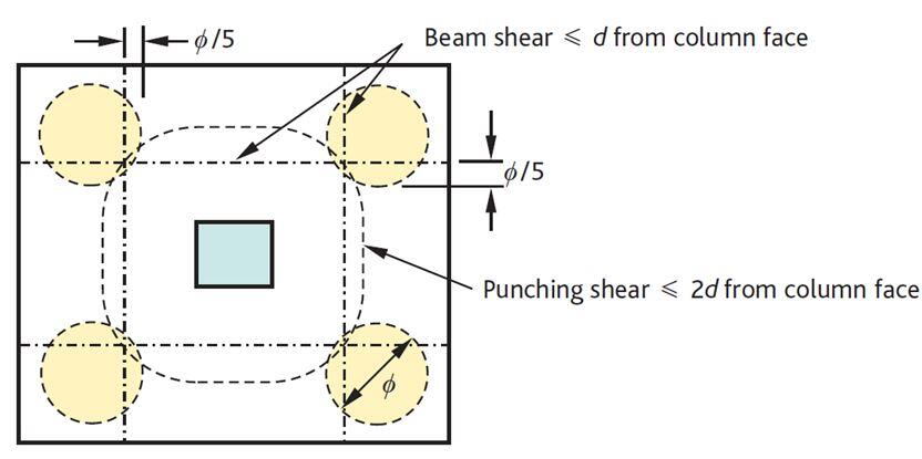
Consider the critical section for shear to be located at 20% of the pile diameter inside the pile cap.
Distance of this section from the column face;
av = 0.5(Spacing between piles – width of column) – 0.3(pile diameter)
av = 0.5(2700 – 1200) – 0.3(900) = 480 mm
Length of corresponding perimeter for punching shear
u = 4(2160) = 8640 mm
Perimeter of pile cap = 4(3900) = 15600 mm
The contribution of the column load to the shear force may be reduced by applying a factor β = av/2d, since av < 2d where 0.5d ≤ av ≤ 2d
But a little consideration will show that av(480 mm) < 0.5d(900 mm), therefore, take av as 0.5d (900)
Therefore β = 900/2(1800) = 0.25
v = βV/bd
V = 6001.483/4 = 1500.37 kN
v = (0.25 x 1500.37 x 103)/(1000 x 1800) = 0.208 N/mm2
VRd,c = [CRd,c.k.(100ρ1 fck)(1/3)]
Where;
CRd,c = 0.18/γc = 0.18/1.5 = 0.12
k = 1 + √(200/d) = 1 + √(200/1800) = 1.33 > 2.0, therefore, k = 1.33
ρ1 = As/bd = 3573/(1000 × 1800) = 0.001985 < 0.02
VRd,c = [0.12 × 1.33(100 × 0.001985 × 40)(1/3)]= 0.318 N/mm2
Since VRd,c (0.318 N/mm2) > VEd (0.208 N/mm2), No shear reinforcement is required Okay.
Step 7: Check for Anchorage Length
Let us calculate the design tension anchorage length of H32mm bar (fyk = 500 N/mm2, concrete cover = 100 mm, Concrete cylinder strength fck = 40 N/mm2) for a bent bar assuming good bond conditions.
lbd = α1 α2 α3 α4 α5 lb,req ≥ lb,min
lb,rqd = (ϕ/4) σsd/fbd
fbd =2.25η1 η2 fctd
η1 = 1.0 ‘Good’ bond conditions
η2 = 1.0 bar size ≤ 32
fctd = (αct fctk 0.05)/γc
where;
fctk 0.05 = characteristic tensile strength of concrete at 28 days = 2.5 N/mm2 (Table 3.1 EC2)
γc = partial (safety) factor for concrete = 1.5
αct = coefficient taking account of long-term effects on the tensile strength, this is an NDP with a recommended value of 1.
fctd = (1.0 × 2.5)/1.5 = 1.667 N/mm2
fbd = 2.25 × 1.0 × 1.0 × 1.667= 3.75 N/mm2
lb,rqd = (ϕ/4) σsd/fbd
σsd = 0.87 × 500 = 435 N/mm2
lb,rqd = (ϕ × 435 )/(4 × 3.75) = 29ϕ
Therefore;
lbd = α1 α2 α3 α4 α5(29ϕ) (see Table 8.2 EC2)
For a bent bar
α1 = 1.0 (Cd = 75 mm is ≤ 3ϕ = 3 × 32 = 96 mm)
α2 = 1.0 – 0.15 (Cd – 3ϕ)/ ϕ = 0.901 < 1.0
α3 = 1.0 conservative value with k = 0
α4 = 1.0 N/A
α5 = 1.0 conservative value
lbd = 0.9 × (29ϕ) = 26.1ϕ = 26.1 × 32 = 835 mm
With the effective depth of 1800 mm, the pile dimension will satisfy the anchorage requirements.






I love this,will love to see example on calculation of bridge column design