Many problems of practical importance can be related to the solution of plates resting on an elastic foundation. Reinforced concrete pavements of highways and airport runways, raft foundation slabs of buildings, bases of water tanks and culverts etc., are well-known direct applications. Just like beams on elastic foundation, it is also based on the assumption that the foundation’s reaction q(x, y) can be described by the following relationship;
q(x, y) = kw
Where k is a constant termed the modulus of subgrade reaction, which has the unit (kN/m2/m), and q(x, y) is the resisting pressure of the foundation, and w is the deflection of the plate.
When the plate is supported by a continuous elastic foundation, the external load acting in the lateral direction consists of the surface load p(x, y) and of the reaction of the elastic foundation q(x, y). Thus, the differential equation of the plate becomes the following:
(∂4w)/∂x4 + 2(∂4w)/(∂x2∂y2) + (∂4w)/∂y4 = (1/D) x [p(x,y) – q(x,y)]
In this differential equation, the reactive force, q(x, y) exerted by the elastic foundation is also unknown, because it depends on the deflection, w(x, y) of the plate.
D∇2 ∇2w + kw = p
This equation can be solved using the classical methods developed by Navier and Levy. Note that D is the flexural rigidity of the plate, and it is given by;
D = Eh3/[12(1 – μ2)]
The different methods that can be employed in the analysis of plates on elastic foundation are;
- Classical methods
- Finite difference methods
- Finite element method
Cylindrical bending of plates on elastic foundation
Let us consider the cylindrical bending of a thin plate on an elastic foundation, and rigidly supported at the edges as given in Timoshenko.
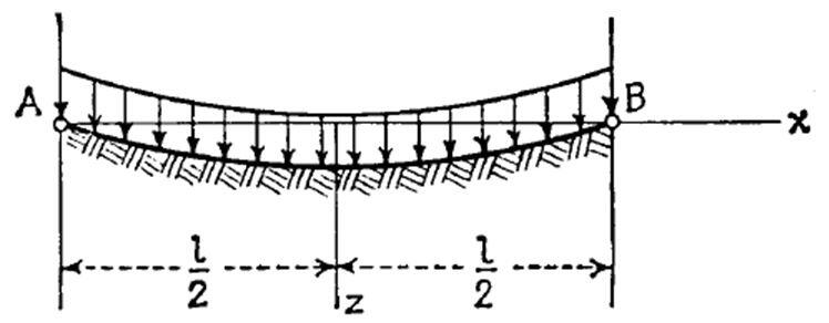
Cutting out an elemental strip, we may consider it as a beam on an elastic foundation. Assuming that the reaction of the foundation at any point in time is proportional to the deflection w at that point, we can obtain the equation given below;
D(∂4w)/∂x4 = q – kw
Introducing the notation;
β =L/2 ∜(k/4D)
The general solution to the equation above can be written as;
w = q/k + C1sin2βx/L sinh2βx/L + C2sin2βx/L cosh2βx/L + C3cos2βx/L sinh2βx/L + C4cos2βx/L cosh2βx/L —- (1)
Where the four constants of integration must be determined from the end conditions of the strip. With the case under consideration, we can assume that the deflection is symmetrical with respect to the middle strip. Taking the coordinate axis as shown in the figure above, we can conclude that C2 = C3 = 0. The constants C1 and C4 are found from the conditions that the deflection and bending moment of the strip are zero at the end (x = L/2). Hence;
w(x=l/2) = 0
(d2w)/dx2 )(x = l/2) = 0
Substituting expressions (a) for w and observing that C2 = C3 = 0, we obtain;
q/k + C1sinβsinhβ + C4cosβcoshβ = 0
C1cosβcoshβ – C4sinβsinhβ = 0
From which we find;
C1 = -q/k (2sinβsinhβ)/(cos2β + cosh 2β)
C2 = -q/k (2cosβcoshβ)/(cos2β + cosh 2β)
On substituting into equation (1);
w = qL4/64Dβ4 ∙{1 – [(2sinβsinhβ)/(cos2β + cosh2β) ∙sin2βx/L∙sinh2βx/L] – [(2cosβcoshβ )/(cos2β + cosh2β)∙cos2βx/L∙cosh2βx/L)]} — (2)
The deflection at the middle is obtained by substituting x = 0, which gives;
w(x=0) = (5qL4/384D)∙φ(β)
Where;
φ(β) = 6/5β4 ∙[1 – (2 cosβcoshβ )/(cos2β + cosh 2β)]
To obtain the angles of rotation of the edges of the plate, we differentiate expression (2) with respect to x and put x = -L/2.
In this way we obtain;
(dw/dx)(x= -l/2) = (5qL4/384D)∙φ1(β)
Where φ1(β) = 3/4β3 ∙ [1 – (sinh2β – sin2β)/(cosh2β + cos2β)]
The bending moment at any cross-section of the strip is obtained from the equation;
M = -D(d2w/dx2)
Substituting expression (D) for w, we find for the middle strip;
M(x=0) = (qL2/8)∙ φ2(β)
Where φ2(β) = 2/β2 [1 – (sinhβ – sinβ)/(cosh2β + cos 2β)]
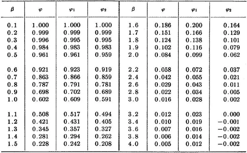
To simplify the calculation of deflection and stresses, numerical values of functions of φ, φ1, and φ2 are presented in the Table below;
Plates on Elastic Foundation Using Finite Element Analysis
Software like Staad Pro can be used in the analysis of plates on elastic foundation. The general approach to solving such problems is to sub-divide the slab into several plate elements. Each node of the meshed slab will then have an influence area or a contributory area, which is to say that soil within the area surrounding that node acts as a spring. The influence area is then multiplied by the subgrade modulus to arrive at the spring constant. Subgrade modulus has units of force per length3. So, the spring will have units of force/length.
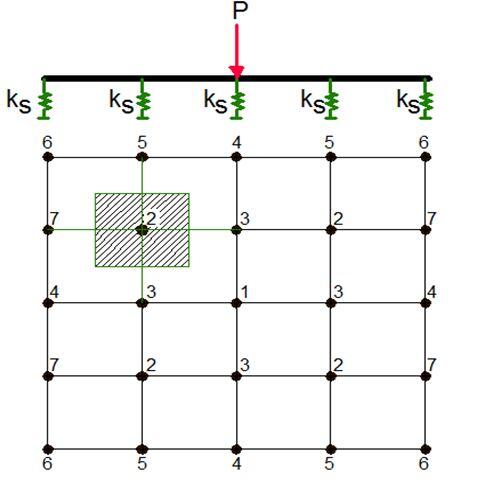
The influence area is calculated automatically in Staad Pro using the ‘Foundation’ type of support. The two options available for doing this are of doing this are;
- ELASTIC MAT OPTION, and
- PLATE MAT OPTION
The elastic mat method calculates the influence area of the various nodes using the Delaunay triangle method. The distinguishing aspect of this method is that it uses the joint-list that accompanies the ELASTIC MAT command to form a closed surface. The area within this closed surface is then determined and the share of this area for each node in the list is then calculated. Without a properly closed surface, the area calculated for the region may be indeterminate and the spring constant values may be erroneous.
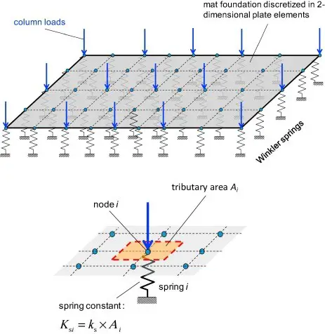
If the foundation slab is modeled using plate elements, the influence area can be calculated using the principles used in determining the tributary area of the nodes from the finite element modeling standpoint. In other words, the rules used by the program in converting a uniform pressure load on an element into fixed end actions at the nodes are used in calculating the influence area of the node, which is then
multiplied by the subgrade modulus to obtain the spring constant.
Solved Example
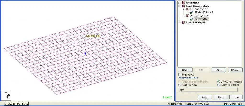
A 150 mm thick rectangular slab of dimensions 6m x 5m is resting on a soil of modulus of subgrade reaction ks = 30000 kN/m2/m. Evaluate the response of the slab when subjected to a full pressure load of 35 kN/m2 all over the surface and a concentrated load of 200 kN at the centre.
Solution
The meshing of the plate has been carried out as follows;
In the longer direction: 24 divisions
In the shorter span: 20 divisions
Size of each finite element = 250 mm x 250 mm
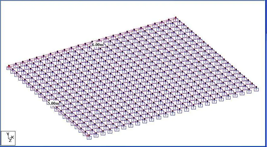
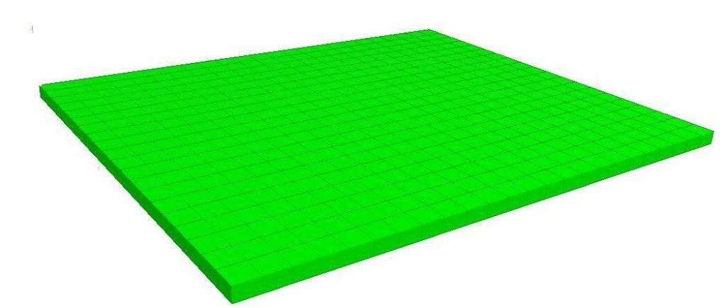
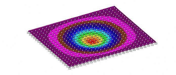
The modelling of the foundation is shown below;
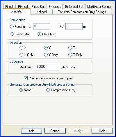
The loading of the plate is shown below.
Analysis Result
(a) Settlement
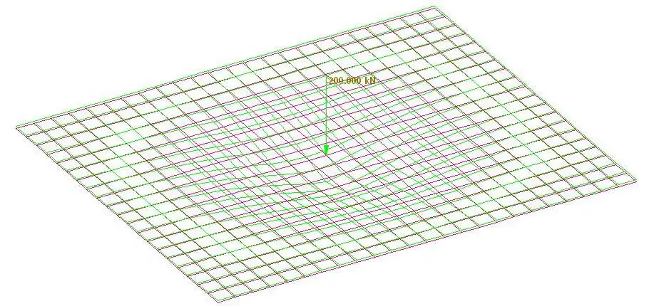
Maximum settlement under concentrated load = 1.912 mm
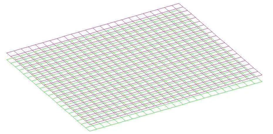
Maximum settlement under uniform pressure load = 1.167 mm
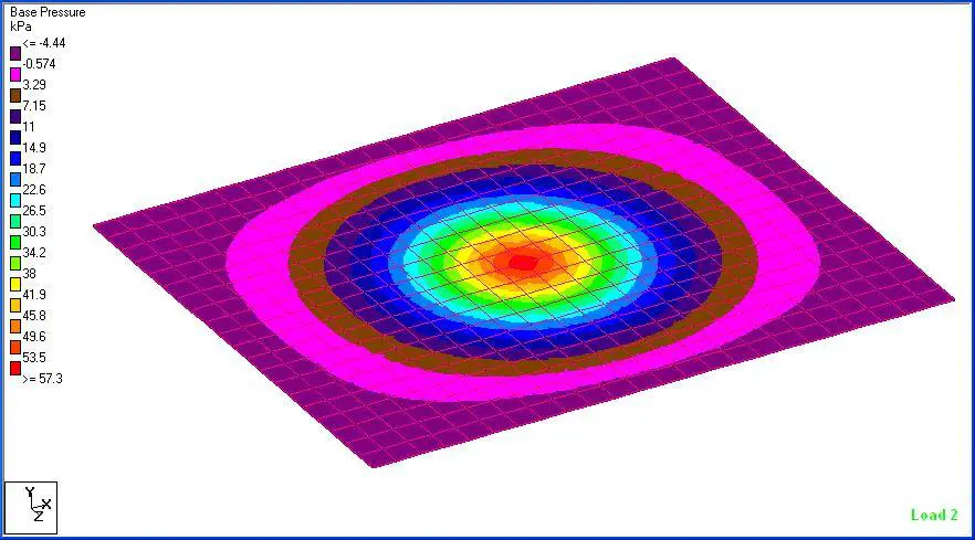
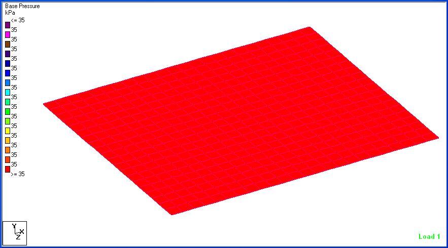
(b) Base Pressure
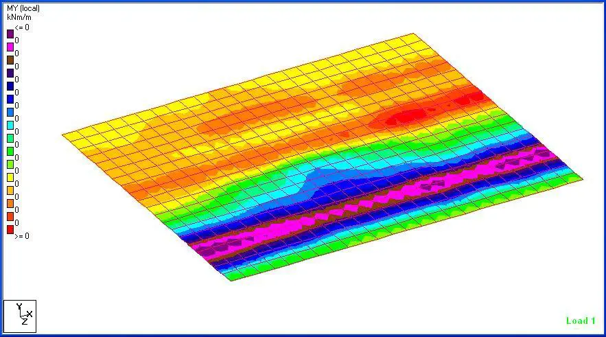
(c) Bending Moment
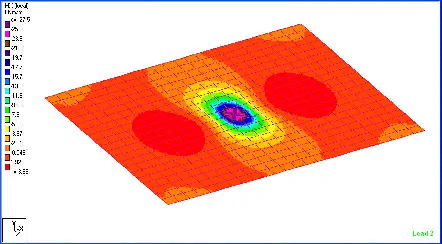
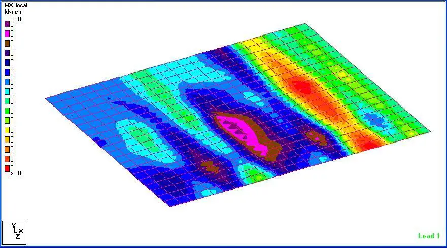
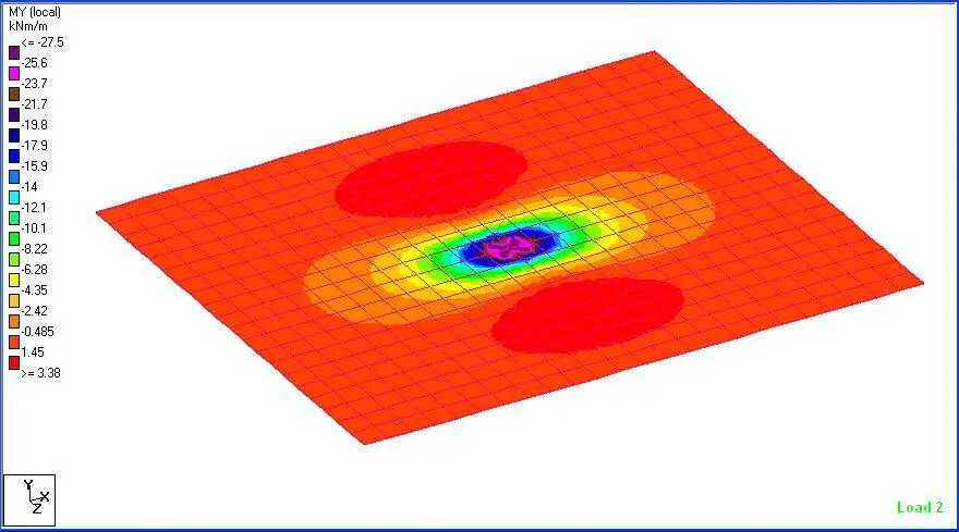





This is simply good and very helpful.
I am interested in meeting you face to face sir.