Vibration analysis of floors is not entirely new in the field of structural engineering. Numerous studies and researches have been devoted to human-structure interaction, with emphasis on human perception of vibration in civil engineering structures. Recently, the quest for construction of slender structures with large unobstructed areas (with flexible partitioning) has made the idea of vibration serviceability very important in the design of structures. Once a building is constructed, it is usually challenging to ameliorate vibration issues since it involves modifying the mass and stiffness of the structure.
In the UK, the vibration sensitivity of composite slabs has been traditionally checked by ensuring that the vertical natural frequency of secondary and primary beams is greater than 4Hz. However, a new approach has been recommended in the publication SCI P354 (2009) for checking the vibration serviceability of composite slabs. An example using the approach has been presented in this article.
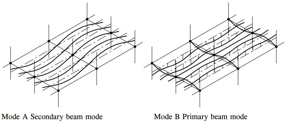
In P354, two modes of vibration have been recommended for checking acceptability. In mode A, alternate secondary spans may be deflecting up and down (assuming simply supported conditions) with the participation of the slabs (as fixed ended) but not the primary beams. The primary beams are assumed to form nodal lines with zero deflection. In mode B, the primary beams may be deflecting in the same manner, but the secondary beams and slabs which are effectively fixed ended contribute to extra deflection. Therefore for mode B, the deflection is a sum of three contributions. The lower frequency of the two modes is taken as the fundamental frequency and should be at least 3Hz to ensure that walking activities will be outside the frequency zone that will cause resonance.
The design procedures for determining the dynamic performance of composite floors is as follows;
- Determine the natural frequency
- Determine the modal mass of the floor
- Evaluate the response of the floor
- Verify the response of the floor against the requirements
Solved Example
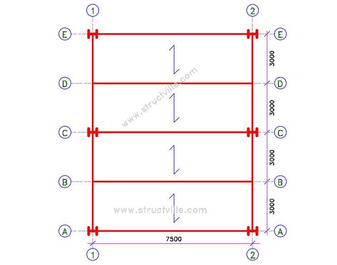
The figure below shows a part plan of a composite floor. The slab is to be constructed using profiled metal decking and normal weight, grade 30 concrete. The longitudinal beams are of grade S275 steel with a span of 7.5 m and spaced 3 m apart. Check the acceptance of the floor for vibration. 406 x 178 x 67 UKB as the internal beams. T
Member Geometry
Primary beams 610 x 229 x 140 UKB
Secondary beams 406 x 178 x 67 UKB
Beam span = 7.5 m
Beam spacing = 3.0 m
Total depth of slab hs = 130 mm
Depth of profile hp = 60 mm
Overall height of profile hd = 72 mm
Depth of concrete above profile = 58 mm
Profile: SMD TR60+ (1.2 mm gauge)
Gauge = 1.2 mm
Mesh: A142
Floor loading
130 mm deep concrete slab = 2.21 kN/m2 (manufacturer’s data)
Self weight of profile decking = 0.131 kN/m2
Ceiling and services = 1 kN/m2
Finishes = 1.2 kN/m2
10% Imposed = (0.1 x 5 kN/m2)= 0.5 kN/m2
Sub total = 5.041 kN/m2
Primary beams = (140 kg/m x 9.81/7.5) x 10-3 = 0.183 kN/m2
Scondary beams = (67 kg/m x 9.81/3) x 10-3 = 0.22 kN/m2
Total = 5.44 kN/m2 = (5.44 x 10³)/9.81 = 554.54 kg/m2

Calculation of composite slab properties

Profile neutral axis = 33.7 mm
Profile area/unit width = 1633 mm2/m
Profile moment of inertia = 119.8 cm4/m
Height of re-entrant rib = 60 mm
Concrete area/unit width for 130 mm thick slab= 0.096 m2/m
Therefore effective slab thickness = 96 mm
For dynamic properties, take the gross uncracked moment of inertia. Dynamic modulus of elasticity of concrete Ecm = 38 kN/mm2.
Modular ratio α = Es/Ecm = 210/38 = 5.526
We can calculate the elastic neutral axis of the composite slab from the table below.
| Section | Area A (cm2) | Neutral axis y (cm) | Area x y (cm3) |
| Concrete | 960/α = 173.724 | 9.6/2 = 4.8 | 816.5 |
| Profile | 16.33 | 13 – 3.37 = 9.63 | 157.257 |
| Total | ∑A = 190.054 | ∑Ay = 973.757 |
Elastic neutral axis of the composite slab NA = ∑Ay/∑A = 973.757/190.054 = 5.123 cm below the top of the slab
The moment of inertia of the composite slab can be calculated from the table below;
| Section | Distance from NA (cm) | Area x Distance2 (cm4) | Iy,local (cm4) |
| Concrete | 0.323 | 18.124 | 3139 |
| Profile | 4.507 | 331.712 | 119.8 |
| 349.836 | 3258.8 |
Second moment of area of composite slab = 349.836 + 3258.8 = 3608.636 cm4 (36.0863 x 10⁻⁶ m4)
Moment of inertia of the composite secondary beam
406 x 178 x 67 UKB
Span = 7.5m; Weight = 67.1 kg/m
Depth = 409.4 mm; Area = 85.5 cm2
Iy = 24300 cm4; Effective breadth beff = 1875 mm
Composite section properties
| Section | Width (cm) | Depth (cm) | y (cm) | A (cm2) | Ay (cm3) | Ay2 (cm4) | Ilocal |
| Slab | 187.5 | 7.0 | 3.50 | 1312.5/5.526 = 237.513 | 831.297 | 2909.532 | 969.847 |
| Beam | 33.47 | 85.5 | 2861.68 | 95780.596 | 24300 | ||
| ∑A = 323.013 | ∑Ay = 3692.977 | ∑Ay2 = 98690.128 | ∑Ilocal = 25269.847 |
Position of elastic neutral axis = ∑Ay/∑A = 3692.977/323.013 = 11.432 cm from the top of the slab
Gross moment of area = 98690.128 + 25269.847 – (11.4322 x 323.013) = 81745.204 cm4 (8.1745 x 10⁻⁴ m4)
Moment of inertia of the composite primary beam
610 x 229 x 140 UKB
Span = 6.0m; Weight = 139.9 kg/m
Depth = 617.2 mm; Area = 178 cm2
Iy = 112000 cm4; Effective breadth beff = 1500 mm
Composite section properties
| Section | Width (cm) | Depth (cm) | y (cm) | A (cm2) | Ay (cm3) | Ay2 (cm4) | Ilocal |
| Slab | 150 | 9.6 | 4.8 | 1440/5.526 = 260.586 | 1250.81 | 6003.9 | 2001.3 |
| Beam | 43.86 | 178 | 7807.08 | 342418.53 | 112000 | ||
| ∑A = 438.586 | ∑Ay = 9057.89 | ∑Ay2 = 348422.43 | ∑Ilocal = 114001.3 |
Position of elastic neutral axis = ∑Ay/∑A = 9057.89/438.586 = 20.652 cm from the top of the slab
Gross moment of area = 114001.3 + 348422.43 – (20.6522 x 438.586) = 275364.5625 cm4 (27.5364 x 10⁻⁴ m4)
Fundamental natural frequency
Mode A
(i) Slab – Fixed Ended
w = 5.041 kN/m2 x 3 m = 15.123 kN/m
δ1 = wL3/384EI = (15.123 x 33)/(384 x 210 x 106 x 36.0863 x 10-6) = 1.403 x 10⁻⁴ m = 0.14 mm
(ii) Secondary beam – Simply Supported
w = (5.041 kN/m2 + 0.22 kN/m2) x 3 m = 15.783 kN/m
δ2 = 5wL4/384EI = (5 x 15.123 x 7.54)/(384 x 210 x 106 x 8.1745 x 10-4) = 3.629 x 10⁻³ m = 3.629 mm
Total deflection for mode A δ = 0.14 + 3.629 = 3.760 mm
Natural frequency for mode A fA = 18/√δ = 18/√3.760 = 9.282 Hz
Mode B
(i) Slab – As above
(ii) Secondary beam (assume fixed ended)
w = (5.041 kN/m2 + 0.22 kN/m2) x 3 m = 15.783 kN/m
δ2 = wL4/384EI = (15.123 x 7.54)/(384 x 210 x 106 x 8.1745 x 10-4) = 7.2589 x 10⁻⁴ m = 0.725 mm
(iii) Primary beam (assume simply supported)
Reactive force from secondary beam = (15.783 x 7.5)/2 = 59.186 kN
w = (5.041 kN/m2 + 0.183 kN/m2) x 3.75 m = 19.59 kN/m
δ3 = 5wL4/384EI + PL3/48EI = [(5 x 19.59 x 64)/(384 x 210 x 106 x 27.5364 x 10-4)] + [(59.186 x 63)/(48 x 210 x 106 x 27.5364 x 10-4)] = (5.716 x 10⁻⁴) + (4.605 x 10⁻⁴) = 1.032 x 10⁻³ m = 1.032 mm
Therefore total deflection = 0.14 + 0.725 + 1.032 = 1.897 mm
Natural frequency for mode B fB = 18/√δ = 18/√1.879 = 13.13Hz
Therefore the fundamental frequency of the floor is found in Mode A f0 = 9.292 Hz > 3.0 Hz (Okay)
Calculation of Modal Mass
The effective floor length can be calculated from;
Leff = 1.09(1.10)ny – 1(EIb/mbf02)1/4 Leff ≤ nyLy
Where;
ny is the number of bays in the secondary beam direction (ny ≤ 4)
EIb is the flexural rigidity of the composite secondary beam (expressed in Nm2 when m is expressed in kg/m2)
b is the spacing of the secondary beam = 3.0 m
f0 is the fundamental natural frequency
Ly is the span of the secondary beams
Leff = 1.09(1.10)1 – 1(210 x 109 x 8.1745 x 10-4/554.54 x 3 x 9.2922)1/4 = 7.049 m < (1 x 7.5 = 7.5 m)
The effective width of the slab can be calculated from;
S = η(1.15)nx – 1(EIs/mf02)1/4
η = 0.71 for f0 > 6.0
nx = 2.0
S = 0.75(1.15)2 – 1 x (210 x 109 x 36.0863 x 10-6/554.54 x 9.2922)1/4 = 3.05 m < (2 x 6 = 12)
Modal mass M = mLeffS = 554.54 x 7.04 x 3.05 = 11907 kg
Calculation of Floor Response
As f0 < 10 Hz, the response is to be assessed according to the low frequency floor recommendations.
aw,rms = μeμr (0.1Q/2√2Mζ) x Wρ
Q = 746 N based on an average weight of 76 kg
Take critical damping ratio ζ as 4.68%
Since f0 > 8Hz, take the weighting factor W = 8/f0 = 8/9.292 = 0.860
Conservatively assume that μe = μr = 1.0
Assuming a walking frequency fp of 2Hz in a maximum corridor length Lp of 15 m;
v = 1.67fp2 – 4.83fp + 4.5 = 1.52 m/s
ρ = 1 – e(-2πζLpfp/v) = 1.0
aw,rms = 1.0 x 1.0 x [(0.1 x 746)/(2√2 x 11907 x 0.0468)] x 0.86 x 1.0 = 0.0407 m/s2
Response Factor
R = aw,rms/0.005 = 0.0407/0.005 = 8.14
For an office building, the floor is is acceptable for vibration since the response factor is greater than 8.0.

