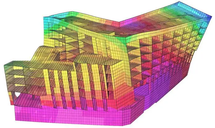
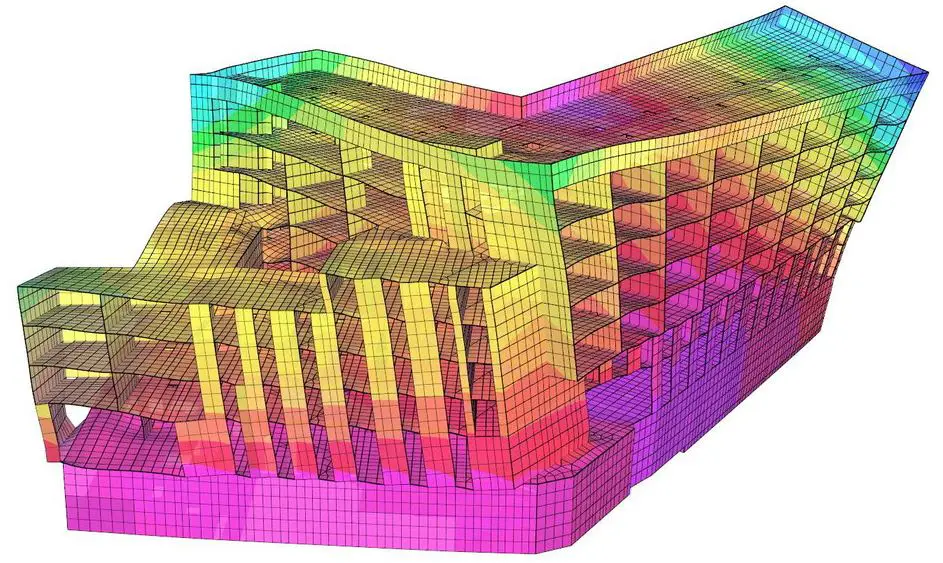
The dynamic performance of a vibrating floor can be accurately assessed through finite element modelling (FEM) of the floor or the entire structure, or by employing similar numerical techniques. FEM approximates a continuous structure by discretizing it into finite elements.
The relationships between these elements are then established using multi-degree-of-freedom system methodologies. While FEM accuracy improves with increased element count, computational complexity and time requirements also escalate accordingly. The major outputs sought from simple dynamic analysis of structures (modal analysis) are the modal frequencies, mode shapes, and modal mass.
This article aims to provide tips and suggestions on how to carry out adequate modelling for accurate dynamic analysis results.
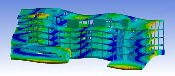
Suggestions for Successful FEM for Dynamic Analysis
Based on extensive comparisons of various composite floor types, the following modelling parameters and details are recommended by Smith et al. (2009) as a foundation for accurate analysis. It is understood that refinements beyond these guidelines can further enhance predictive capabilities.
- The dynamic modulus of elasticity of concrete should be taken as 38 kN/mm2 for normal-weight concrete and 22 kN/mm2 for lightweight concrete.
- Shell elements should be used to model the slab, employing an effective concrete thickness when profiled steel sheeting is incorporated. The slab can generally be assumed to behave as a continuous structural component.
- All structural connections should be assumed rigid for the purposes of vibration analysis. This assumption is justified despite the pinned joint design employed for ultimate limit state considerations, as the relatively low strain levels encountered during vibration do not typically overcome frictional resistance at the connections, resulting in fixed-end behaviour under dynamic conditions.
- In dynamic analysis, column elements should be included in the model and pinned at their theoretical inflexion points, typically located at mid-height between floor levels in multi-story structures.
- Continuous façade cladding can be assumed to impose full vertical restraint on perimeter beams. Consequently, the building edges should be modelled with rotational freedom but restricted movement in all three translational directions, effectively simulating pinned conditions.
- Core walls can be assumed to provide vertical restraint to the floor system. Due to the typically stiff connection between the floor and the core, these interfaces should be modelled as fully restrained.
- The floor mass should be calculated by summing the self-weight, other permanent loads, and a portion of the imposed loads deemed likely to be permanently present.
- Movement joints should be modelled as rotationally free while maintaining a fixed spatial location. While a more precise analysis could incorporate the joint’s stiffness by considering its deflected shape, this level of detail is often computationally inefficient given the typically minor stiffness transfer through such joints.
Accurately determination of floor damping levels presents a significant challenge due to the substantial influence of finishes and non-structural elements. In the absence of more precise data, it is recommended to adopt the damping values specified in this article.
Mesh Refinement for FEM
There are no definitive guidelines for element or mesh size selection in dynamic analysis. However, a general rule of thumb is to consider the mesh sufficiently refined if doubling the number of elements produces negligible changes in calculated frequencies.
FEM of Composite Metal Profile Decking
When modelling composite slabs incorporating profiled steel decking, orthotropic shell elements are the preferred option if available. The slab thickness should be defined as the height of the concrete above the profile (thickness of the concrete topping), while the mass and elastic moduli (for both directions) should be adjusted to account for the additional weight and stiffness contributed by the ribs. Note that the density of the concrete may need to be increased to account for the
weight of the concrete in the ribs.
The modulus of elasticity of the composite section should be calculated using the relationship below:
Ecx = Ec × (12Icx/hc3)
where:
Ic,x is the second moment of area of the profiled slab per metre width in the spanning direction
hc is the depth of concrete above the profile
Ec is the dynamic elastic modulus of concrete
Ideally, an offset beam element should be employed to accurately represent the composite stiffness. However, in the absence of this capability, the composite stiffness can be calculated and applied to the beam element after subtracting the concrete’s contribution. This alternative approach may yield less precise modal property predictions, especially when torsional vibrations are present.

As the slab is modelled using uniform thickness of hc, the offset, hs, is:
hs = ht + ha – zel,a – 0.5hc
where:
ht is the depth of the slab (including the ribs)
ha is the depth of the steel beam
zel,a is the height of the neutral axis of the steel beam.
If an orthotropic slab is not available, the slab should be defined as an isotropic slab with elastic modulus Ecx, as defined above.
Modal Mass
The essential outputs from a dynamic finite element analysis are modal frequencies, mode shapes, and modal masses. Mode shapes can be presented in two formats: mass-normalized and unity-normalized.
Mass-Normalized Mode Shapes: Displacements are scaled such that the modal mass, Mn, equals 1 kg. While suitable for subsequent calculations, this format offers limited insight into a mode’s contribution to the overall response.
Unity-Normalized Mode Shapes: The maximum displacement for each mode is arbitrarily set to 1. To determine the corresponding modal mass, calculate the maximum kinetic energy within the mode (typically obtainable from FE software). The relationship between this kinetic energy and modal mass is:
Mn = KEn/2π2f2
where:
Mn is the modal mass for mode n (kg)
KEn is the maximum kinetic energy in mode n that corresponds to the unity normalised mode shape (kg/s2, or J/m2)
f is the frequency of mode n (Hz).
Some finite element software packages provide mass participation or effective mass values, which differ from modal mass.
Sources and Citation
Smith A. L., Hick S.J. and Devine P. J. (2009): Design of Floors for Vibration: A New Approach. The Steel Construction Institute, UK

