In the construction of any substructure below the ground surface, excavations must be made to the recommended depth before the construction can begin. In the circumstances where deep vertical cuts (say about 3m) are to be made in a soil, provision must be made for the support of the soil to stop it from caving in or collapsing. The design of braced cuts involves the evaluation of the stresses in the members (bracings) used for supporting the cut, and provision of adequate members sizes or sections to avoid structural failure. These are usually classified as temporary works in construction.
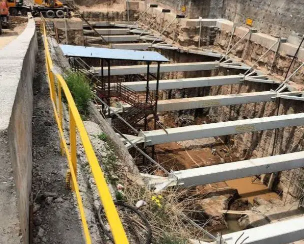
Most shallow foundations in cohesive-frictional soils may not need side supports to keep the cut stable. Furthermore, when there is enough space, the sides of the excavation may be sloped, thereby eliminating the need for bracings or support. However, when a vertical excavation exceeds 3m depth, the most common practice is to drive vertical timber planks called sheeting along the sides of the excavation. Horizontal beams called wales are used to hold the sheeting in place, while struts running from side to side of the excavation is used to hold the wales in place.
For deeper cuts of about 5-6m, the use of timber sheeting may become uneconomical and steel sheet pile walls may be used (see figure below). Sheet piles are convenient to use because of their high resistance to stresses. On the other hand, they are relatively lightweight and reuseable when compared with timber.
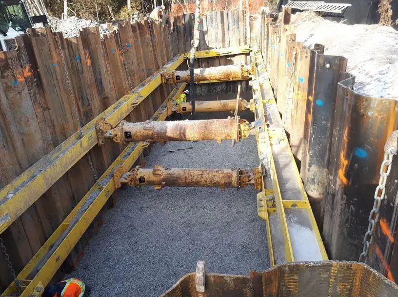
The sheet piles are driven around the boundary of the excavation. As the soil is removed from the enclosure, the wales and struts are inserted. The process continues until the excavation is complete. When the width of the excavation is too wide to permit the economical use of struts across the excavation, tiebacks may be used as shown below.
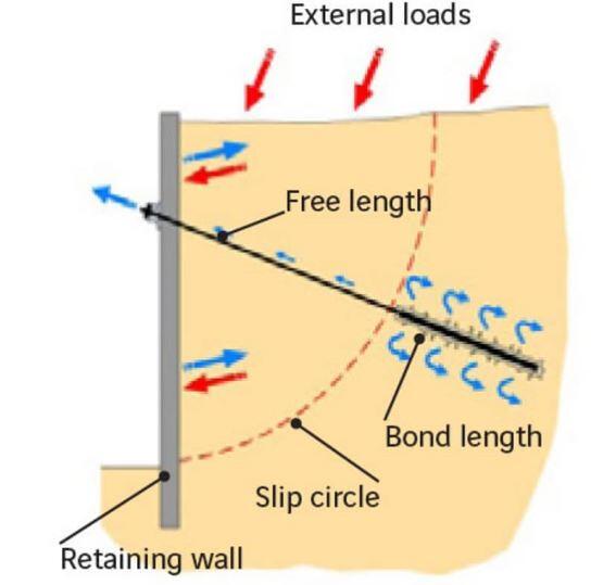
Lateral Earth Pressure Distribution in Braced Cuts
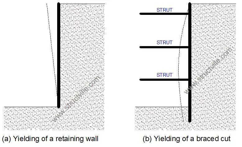
To design braced excavations (that is to select the wales, struts, sheet piles etc), the engineer must estimate the lateral pressure that the braced cut will be subjected to. The lateral earth pressure distribution of braced cuts is different from that of conventional retaining walls. This is because the deformation of braced cut walls gradually increases with the depth of the excavation. The deformation is influenced by factors such as type of soil, type of equipment used, depth of excavation, and workmanship.
Due to very little wall yielding at the top of the excavation, the pressure will be very close to at rest at the top. At the bottom of the wall with greater yielding, the lateral earth pressure will be lower than the Rankine active earth pressure. As a result of this, the earth pressure distribution of braced cuts varies significantly with that of retaining walls.
Peck in 1969 presented the pressure distribution diagram of braced cuts. The diagrams were developed from observations and studies obtained from the strut load of Berlin subway cut, Munich subway cut, and New York subway cut. He described the pressure as apparent pressure envelopes which represents the fictitious pressure distributions for estimating the strut loads in a braced cut.
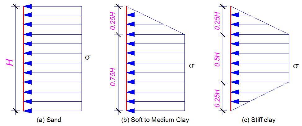
(a) For cuts in sand
The lateral pressure for cuts in sand is given by;
σ = 0.65γHKa
Where;
γ = Soil unit weight
H = Height of the cut
Ka = Rankine’s active earth pressure
(b) For cuts in soft-medium clay (γH/c > 4)
The lateral pressure is the larger of;
σ = γH[1 – (4c/γH)] or σ = 0.3γH
(c) For cuts in stiff clay (γH/c ≤ 4)
σ = 0.2γH to 0.4γH (average of 0.3γH)
Where c is the undrained cohesion of the soil.
When using the pressure envelops in design, it is very important to keep the following in mind;
- The pressure envelope is sometimes referred to as the apparent pressure envelope. The actual pressure distribution depends on the construction sequence and the flexibility of the wall.
- The water table is below the bottom of the cut
- Sand is assumed to be drained with no pore water pressure
- Clay is assumed to be undrained, and pore water pressure is not considered
- The excavation depth is greater than about 6 m
Design of the various components of a braced cut
Struts
Struts in braced cuts behave like horizontal columns. Hence, the load-carrying capacity depends on the slenderness ratio and flexural buckling capacity. During construction, it is recommended that struts should have a minimum vertical spacing of 3m. In clay soils, the depth of the first strut below the ground surface should be less than the depth of the tensile crack.
To determine the load in the strut, the following procedure can be used;
- Draw the pressure envelope of the braced cut and show the strut levels. Assume that the sheet pile walls are hinged at the strut levels except for the top and bottom ones.
- Determine the support reaction of the cantilever (for the top and bottom struts), and use simply supported assumption to determine the intermediate struts
- Sum up the reactions to determine the load in each strut
- Provide and appropriate section for the strut using a suitable design code
Sheet Piles
The following steps may be taken in the design of a sheet pile wall;
- For each of the section (in plan), determine the maximum bending moment
- Pick the highest value of the maximum bending moments (in kNm/m)
- Obtain the required section modulus of the sheet pile wall Sx = Mmax/Allowable stress of the sheet pile material
- Choose a sheet pile section with a slightly higher section modulus
Wales
Wales may be treated as continuous horizontal members if they are properly spliced. Conservatively, they can be assumed to be pinned at the struts.
Design of Braced Cuts – Solved Example
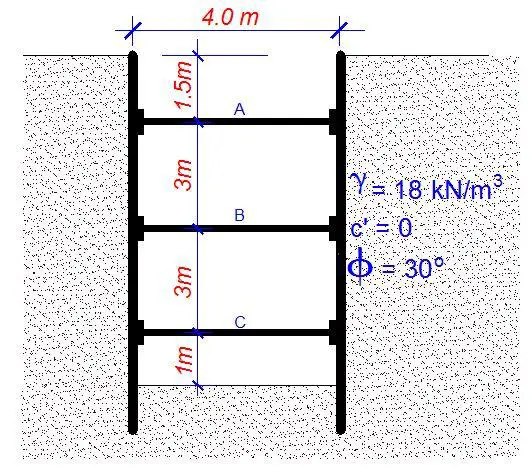
A long trench is excavated in a medium dense sand for the basement of a highrise building. The excavation is supported with sheet pile walls held in place by struts and wales as shown in the figure below. The struts are spaced 4m c/c in plan.
Determine;
(a) The pressure envelope on the wall
(b) The loads in the struts
(c) The maximum moment for determining an appropriate section for the sheet piles
(d) The maximum moment for determining the section for the wales
Solution
(a) The pressure envelope on the wall
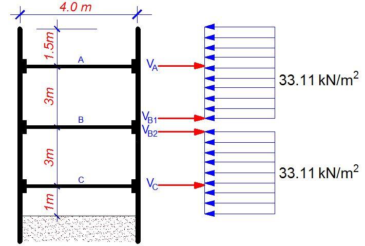
For a braced cut in sand, the apparent pressure envelope is given by;
σ = 0.65γHKa
Ka = (1 – sin30)/(1 + sin 30) = 0.333
σ = 0.65 × 18 × 8.5 × 0.333 = 33.11 kN/m2
(b) Calculation of the strut load
Since the struts are spaced at 4m c/c in plan, the UDL = 33.11 × 4 = 132.44 kN/m
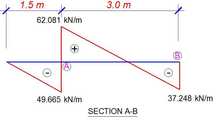
Section A – B
Taking moment about A;
3VB1 – (33.11 × 32)/2 + (33.11 × 1.52)/2 = 0
VB1 = 111.746/3 = 37.248 kN/m
Taking moment about B;
3VA – (33.11 × 4.52)/2 = 0
VA = 335.238/3 = 111.746 kN/m
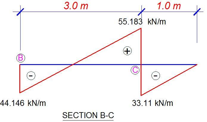
Section B – C
Taking moment about C;
3VB2 – (33.11 × 32)/2 + (33.11 × 1.02)/2 = 0
VB2 = 132.44/3 = 44.146 kN/m
Taking moment about B;
3VC – (33.11 × 42)/2 = 0
VC = 264.88/3 = 88.293 kN/m
The shear force diagrams of the different sections are shown below;
In summary the strut loads are as follows;
VA = 111.746 kN/m × 4m = 446.985 kN
VB = VB1 + VB2 = 37.248 kN/m + 44.146 kN/m = 81.394 kN/m × 4m = 325.576 kN
VC = 88.293 kN/m × 4m = 353.173 kN
When the loads are factored, the struts can be designed as axially loaded steel columns.
(c) Bending moment on the sheet pile walls
By looking at the shear force diagram, we can confirm that the maximum moment will occur at the cantilever regions and at the points of contraflexure for shear.
For section A-B, the point of contraflexure of the shear force diagram can be obtained using similar triangle;
62.081 = (3 – x)
37.248 = x
On solving, x = 1.125 m from point B
Similarly for section B-C;
55.183 = (3 – x)
44.146 = x
On solving, x = 1.333 m from point B
Hence;
MA = (33.11 × 1.52)/2 = 37.25 kNm/m
MC = (33.11 × 1.02)/2 = 16.55 kNm/m
MA-B,max = (37.248 × 1.125) – (33.11 × 1.1252)/2 = 20.951 kNm/m
MB-C,max = (44.146 × 1.333) – (33.11 × 1.3332)/2 = 29.43 kNm/m
The maximum moment for the section is 37.25 kNm/m and should be used for the design of the sheet pile wall when factored.
(d) Design moment of the wales
We can use the maximum strut load to design the wale.
Mmax = PL2/8
Where L is the spacing of the strut in plan
Mmax = (111.746 x 42)/8 = 223.492 kNm/m
The design can be carried out accordingly.
Special considerations should be given to braced cuts in layered soils (kindly refer to standard geotechnical engineering textbooks). Furthermore, heave at the bottom of braced cuts in clay soils should also be considered where applicable.




Nice breakdown of deep excavation wall support.
One question though, do you have a reference/link to Peck 1969?
wow, it is nice material. i like the way of presentation