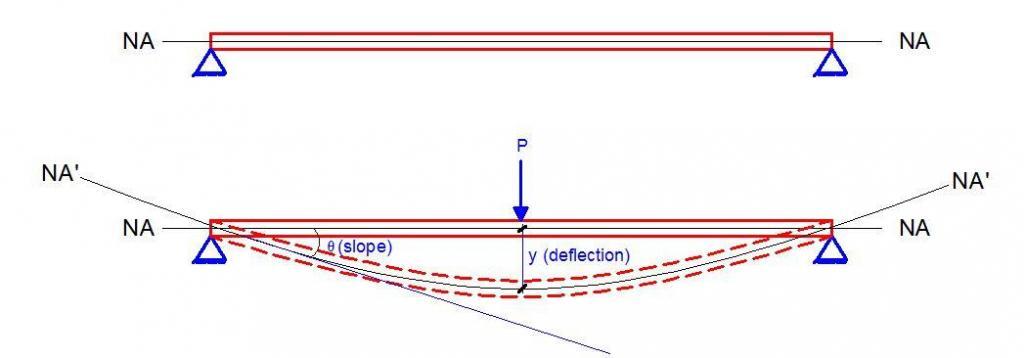
Beams deform when loaded. This deformation is the displacement of the beam section from its original position, and it is usually quantified using two parameters known as slope and deflection. When loaded, the neutral axis of the beam becomes a curved line which is referred to as the elastic curve.
The vertical distance between the elastic curve and the original neutral axis of the beam is known as the deflection, while the angle (in radians) that the original neutral axis makes with the elastic curve is known as the slope.
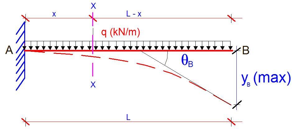
A cantilever is a beam that is rigidly fixed at one end and free at the other. In structural designs, cantilevers are the most sensitive to serviceability issues such as deflection and vibration. There are many ways of assessing the elastic deflection of cantilever beams such as;
- Double integration method
- Moment Area method
- Virtual work method
- Conjugate beam method
- Strain energy method
- Castigliano’s theorem
- Finite element method
- Vereschagin’s method, etc
The aim of this article is to demonstrate the application of Vereschagin’s rule to the evaluation of the deflection of cantilever beams. Vereschagin’s rule is based on the famous Maxwell-Mohr’s integral, but instead of carrying out the actual integration, the bending moment diagram due to the externally applied load is combined with the bending moment due to a unit concentrated virtual load (graph multiplication) to obtain the deflection at that point. Vereschagin’s rule is the graphical method of Maxwell-Mohr’s integral.
This method also forms the backbone of analysing structures using the force method. The charts for combining different types of bending moment diagrams are available in most standard structural engineering textbooks. In the year 2016, I also wrote an article on how to develop the equations on the charts from the first principle. You can download the article from the link below;
Formulation of diagram combination equations based on Vereschagin’s rule
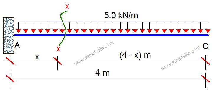
Let us show an example of how this is done using the cantilever beam that is loaded as shown below.

Using the Double Integration Method
Let us cut a section at an arbitary point x-x;
Mx = -5(4 – x)2/2 = -5(4 – x)2/2 —— (1)
EI(∂2y/∂x2) = -Mx = 5(4 – x)2/2 —— (1a)
On integrating equation (1a);
EI(∂y/∂x) = [5(4 – x)3]/6 + C1
At the fixed end A, we know that the slope is equal to zero. Therefore;
At x = 0; ∂y/∂x = 0
⇒ C1 = -53.333
The general equation for the slope of the beam at any point is therefore given by;
EI(∂y/∂x) = [5(4 – x)3]/6 – 53.333 —— (2)
On integrating equation (2), we can obtain the equation for the deflection of the beam at any point;
EI(y) = [-5(4 – x)4]/24 + 53.333x + C2
At the fixed end A, we know that the deflection is equal to zero. Therefore;
At x = 0, y = 0
C2 = -53.333
Hence, the general equation for deflection is;
EI(y) = [-5(4 – x)4]/24 + 53.333x – 53.333 —— (3)
Using equations (2) and (3), the slope and deflection at any point along the beam can be obtained.
At the free end (point C) where x = L = 4 m;
The slope at point C is given by;
EIϴC = [5(4 – 4)3]/6 – 53.333 = -53.333
ϴC = -53.333/EI radians
The deflection at point C is given by;
EIyc = [-5(4 – 4)4]/24 + 53.333x – 53.333 = 53.333(4) – 53.333 = 160
yc = 160/EI metres
Similarly, we can attempt to obtain the deflection at point B using equations (1) and (2);
At point B where x = 3 m;
The slope at point B is given by;
EIϴB = [5(4 – 3)3]/6 – 53.333 = -52.5
ϴB = -52.5/EI radians
The deflection at point B is given by;
EIyB = [-5(4 – 3)4]/24 + 53.333x – 53.333 = -0.208 + 53.333(3) – 53.333 = 106.457
yB = 106.457/EI metres
Using Vereschagin’s Rule (Graphical Method)
Step 1
The first step of the process is to draw the bending moment diagram due to the externally applied load.
A little calculation will show that the maximum moment will occur at the fixed end of the cantilever and it is given by MA = -qL2/2 = (5 × 42)/2 = -40 kNm

Step 2
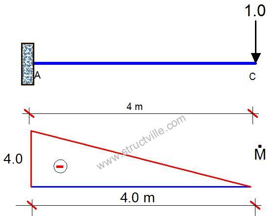
The second step is to place a vertical unit concentrated load at the point we want to obtain the deflection and draw the bending moment diagram due to the unit load. To obtain the slope at any point, we apply a unit moment (rotation) instead of a unit vertical load.
For instance, if we want to obtain the vertical deflection at point C, we remove the externally applied load and replace it with a unit vertical load at point C as shown below. The bending moment diagram obtained from this step is expected to be linear.
Step 3
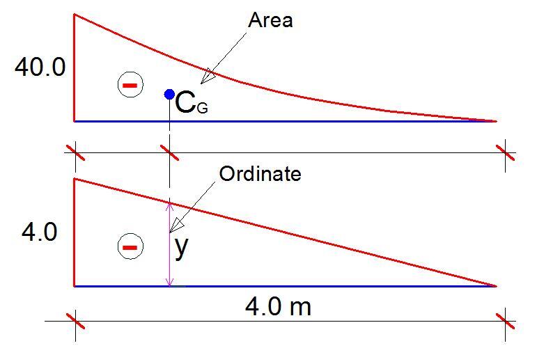
The next step is to combine the bending moment diagram due to the externally applied load with the bending moment diagram due to the unit load. In principle, this combination involves multiplying the area of the principal bending moment diagram with the ordinate that the linear bending moment diagram makes with the centroid of the principal diagram. This is shown below;
You may not really have to stress yourself determining the area and centroid of different shapes because tables are readily available for most of the diagrams encountered during analysis.
For the shapes shown above, the combination equation is given by;
EIyc = 1/4 × M × Ṁ × L = 1/4 × 40 × 4 × 4 = 160
yc = 160/EI metres
You can confirm that this is similar to the answer obtained using the double integration method.
To obtain the slope at point C, we apply a unit rotation at point C and plot the moment diagram as shown below;
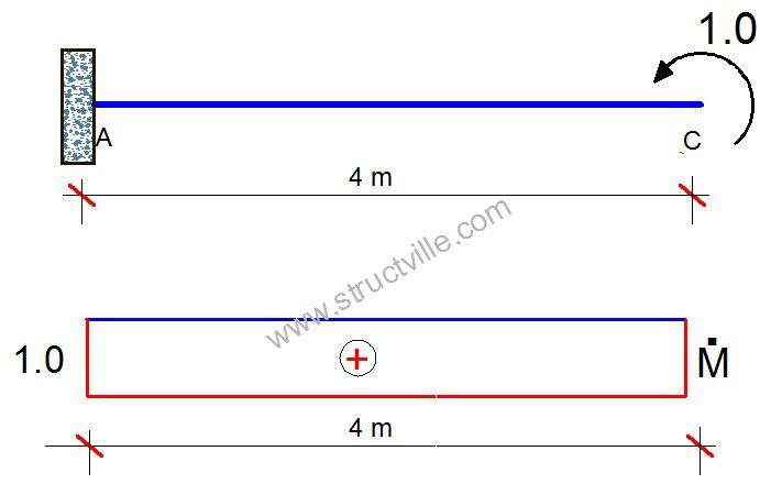
The diagram combination will now be;

From structural engineering tables;
EIϴC = -1/3 x 40 x 4 x 1 = -53.333
ϴC = -53.333/EI radians
As you can see, the Vereschagin’s method is the quickest way of assessing the deflection of statically determinate structures, provided that the combination tables for bending moment diagrams are available.


