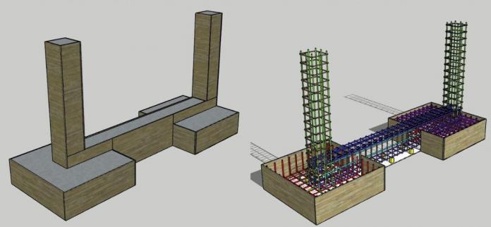
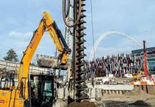
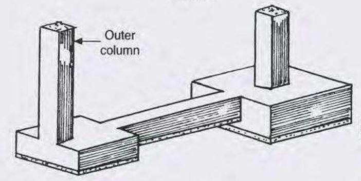
Strap footings or cantilever footings are a special form of combined footings. They consist of two separate bases that are connected (balanced) by a strap beam. In the design of strap footing, it is assumed that the strap beam is rigid and does not transfer any load by bearing on the soil at its bottom contact surface.
Strap footing is necessary when the foundation of a column cannot be built directly under the column or when the column should not exert any pressure below. It is then necessary to balance it by a cantilever arm rotating about a fulcrum and balanced by an adjacent column (or a mass of concrete or by piles) in case of where footings cannot be built.
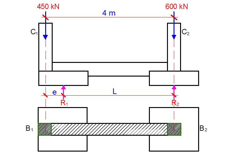
As was described above, balanced footings consist of two separate footings connected by a strap beam. In the design of balanced bases, uniform soil pressure can be assumed if we can make the centre of the areas of the system coincide with the centre of gravity of the loads. When these two centres do not coincide, we have the vertical load and moment acting on the system due to the eccentricity. As a result, the distribution of base pressure will not be uniform but can be assumed to be linearly varying.
The difference between balanced footings and cantilever footings can be described as follows. In a balanced footing, we make the centre of gravity of the loads and the centre of the areas coincide. Hence, the ground pressure will be uniform. In cantilever footings, in general, the two centres may not coincide, so we have a moment in addition to the vertical loads. Hence, the ground pressure will be varying.
Worked Example
Two columns with the following loading conditions are spaced 4 m apart. Due to site boundary constraints, design a strap footing for the columns, if the safe bearing capacity of the soil is 150 kN/m2; fck = 25 N/mm2; fyk = 500 N/mm2
| Column | Size (mm) | Service Load (kN) | Ultimate Load (kN) |
| C1 | 300 x 300 | 450 | 617 |
| C2 | 300 x 300 | 600 | 822 |
Solution
We can either dimension each of the footings so that the CG of the areas and loads coincide, resulting in uniform pressure, or adopt
suitable base dimensions and then check the resulting ground pressure taking the unit as a whole, which may not be uniform, and design for non-uniform pressure. We will adopt the first method.
Step 1: Preliminary sizing of the footing of the exterior column
Base area (A1) needed for column C1 = Service load/Safe bearing capacity = 450/150 = 3m2
Try a rectangular footing of size 1.75m wide x 2 m long along the centre line (Area provided = 3.5 m2)
Hence, we fix the fulcrum at 2.0/2 = 1.0 m from the end near C1.
Therefore;
Distance of R1 from C1 = L1 = 1.0 – 0.3 = 0.7 m from C1
Distance of C2 from R1 = L2 = 4 – 0.7 = 3.3 m
Taking moment about C2;
3.3R1 = 450 x 4
R1 = 545.45 kN
Let the summation of the vertical forces be equal to zero;
R2 = 450 + 600 — 545.45 = 504.55 kN
Step 2: Check the factor of safety (FOS) against overturning using characteristic loads
FOS = C2L2/C1L1 = (600 x 3.3)/(450 x 0.7) = 6.285 > 1.5 (Okay).
Step 3: Find the dimension of footing for R2 so that the CG of loads and areas coincides.
This is given by;
B = √(R2/SBC) = √(504.55/150) = 1.83 m
Adopt a footing 1.85 m x 1.85 m
Step 4: Recalculate the necessary breadth of footing F1 so that CG of loads and areas of footings coincides.
x1 = CG of loads = (C1 x 4)/(C1 + C2) = (450 x 4)/(450 + 600) = 1.714 m from C2
Let us find the CG of areas we have assumed.
Area of F2 = A2 = 1.85 x 1.85 = 3.4225 m2. Find Ax required for CG to be same as that of loads.
x2 = (A1 x 3.3)/(A1 + A2) = 1.714 (for a balanced base)
(A1 x 3.3)/(A1 + 3.4225) = 1.714
On solving; A1 = 3.698 m2
For a length of 2m, a width of 3.689/2 = 1.85 m is required.
Therefore slightly increase the width of A1 to 1.85 m.
Hence;
A1 = (1.85 x 2)m = 3.7 m2
A2 = (1.85 x 1.85)m = 3.4225 m2
Step 5: Calculate uniform pressure for factored load
qnet = (617 + 822)/(3.7 + 3.4225) = 202.03 kN/m2
You can verify independently;
At ultimate limit state; R1 = (545.45 x 617)/450 = 747.87 kN
Soil pressure under base 1 = 747.87/3.7 = 202.13 kN/m2
At umtimate limit state R2 = (504.55 x 822)/600 = 691.23 kN
Soil pressure under base 2 = 691.23/3.4225 = 201.967 kN/m2
Step 6: Design of footing F1
Let the width of the strap beam be 0.3 m. The maximum moment will occur at the face of the strap beam (overhang of the strap beam).
Length of overhang = (1.85 – 0.3)/2 = 0.775 m on both sides of the beam
MEd = ql2/2 = (202.13 x 0.7752)/2 = 60.7 kNm
Assuming a footing depth h = 400 mm and concrete cover of 50 mm;
Effective depth d = 400 – 50 – 8 = 342 mm.
Critical design moment at the face of the strap beam
MEd = 125 kNm/m
k = MEd/(bd2fck) = (60.7 x 10⁶)/(1000 x 3422 x 25) = 0.0207
Lever arm = z = d[0.5 + √(0.25 – 0.882k)] = 0.95d
⇒ z = 0.95d = 0.95 x 342 = 325 mm
⇒ As = MEd/0.87fykz = (60.7 x 10⁶)/(0.87 x 500 x 325) = 429 mm2/m
Asmin = 520 mm2/m
Provide H12 @ 200 c/c (Asprov = 565 mm2/m)
Beam shear
Check critical section d away from the face of the strap beam
VEd = 202.13 x (0.775 – 0.342) = 87.522 kN/m
vEd = 87.522/342 = 0.256 N/mm2
vRd, c = CRd, c × k × (100 × ρ1 × fck) 0.3333
CRd, c = 0.12
k = 1 + √ (200/d) = 1 + √ (200/342) = 1.76
ρ = 565/(342 × 1000) = 0.00165
vRd, c = 0.12 × 1.76 × (100 × 0.00165 × 25)0.333 = 0.338 N/mm2
=> vEd (0.256 N/mm2) < vRd,c (0.338 N/mm2) beam shear ok
Step 7: Design of the strap beam
Equivalent line load under column base 1 = 202.13 x 1.85 = 373.94 kN/m
Equivalent line load under column base 2 = 202.13 x 1.85 = 373.94 kN/m
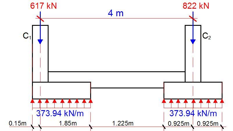
The shear force values at the critical points are;
V1L = (0.15 x 373.94) = 56.09 kN
V1R = 56.09 – 617 = -560.9 kN
Vi = (373.94 x 2) – 617 = 130.88 kN
V2L = 130.88 + (373.94 x 0.925) = 476.774 kN
V2R = 476.774 – 822 = -345.226 kN
Vj = -345.225 + (373.94 x 0.925) = 0
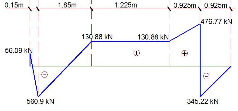
The maximum bending moment will occur at the point of zero shear which is 1.5 m from column A. This can be easily obtained by using similar triangles.
Mmax = (373.94 x 1.652)/2 – (617 x 1.5) = -416.474 kNm (hogging moment).
The maximum sagging moment will occur under column C2;
Mmax = (373.94 x 0.9252)/2 = 159.976 kNm
Assume a total depth of 600 mm for the beam;
Effective depth = 600 – 50 – 10 – 10 = 530 mm
k = MEd/(bd2fck) = (416.474 x 10⁶)/(300 x 5302 x 25) = 0.1976
Since k < 0.167, compression is required. This means that the beam will have to be designed as a doubly reinforced beam.
Area of compression reinforcement AS = (MEd – MRd) / (0.87fyk (d – d2))
MRd = 0.167fckbd2 = (0.167 × 25 × 300 × 5302) × 10-6 = 351.827 kNm
d2 = 50 + 10 + 10 = 70 mm
AS2 = ((416.474 – 351.827) × 106) / (0.87 × 500 × (530 – 70)) = 323 mm2
Asmin = 234 mm2
Provide 4H16 Bottom (Asprov = 804 mm2)
Confirm that this reinforcement can satisfy for bending under column C2.
Area of tension reinforcement As1 = MRd / (0.87fyk z) + AS2
Where z = d[0.5+ √(0.25 – 0.882K’)]
K’ = 0.167
z = d[0.5+ √((0.25 – 0.882(0.167))] = 0.82d
As1 = MRd/(0.87fyk z) + AS2 = (351.827 × 10⁶) / (0.87 × 500 × 0.82 × 530) + 323 mm2 = 2184 mm2
Provide 8H20 Top (ASprov = 2512 mm2)
Shear Design
Using the maximum shear force for all the spans
Support A; VEd = 560.9 kN
VRd,c = [CRd,c.k. (100ρ1 fck)1/3 + k1.σcp]bw.d
CRd,c = 0.18/γc = 0.18/1.5 = 0.12
k = 1 + √(200/d) = 1 + √(200/530) = 1.61 > 2.0, therefore, k = 1.61
Vmin = 0.035k3/2fck1/2
Vmin = 0.035 × 1.613/2 × 251/2 = 0.357 N/mm2
ρ1 = As/bd = 1256/(300 × 530) = 0.007899 < 0.02;
VRd,c = [0.12 × 1.61(100 × 0.007899 × 25)1/3] × 300 × 540 = 84597.88 N = 84.597 kN
Since VRd,c (84.597 kN) < VEd (560.9 kN), shear reinforcement is required.
The compression capacity of the compression strut (VRd,max) assuming θ = 21.8° (cot θ = 2.5)
VRd,max = (bw.z.v1.fcd)/(cotθ + tanθ)
V1 = 0.6(1 – fck/250) = 0.6(1 – 25/250) = 0.54
fcd = (αcc fck)/γc = (0.85 × 25)/1.5 = 14.167 N/mm2
Let z = 0.9d
VRd,max = [(300 × 0.9 × 540 × 0.54 × 14.167)/(2.5 + 0.4)]× 10-3 = 384.619 kN
Since VRd,c < VRd,max < VEd
The beam is subjected to high shear load, we need to modify the strut angle.
θ = 0.5sin-1[(VRd,max /bwd)/0.153fck(1 – fck/250)]
(VRd,max /bwd) = 2.418 N/mm2
0.153fck(1 – fck/250) = 3.4425
θ = 0.5sin-1[(2.418/3.4425] = 22.31°
Since θ < 45°, section is OK for the applied shear stress
Hence Asw/S = VEd /(0.87fykzcotθ) = 560900/(0.87 × 500 × 0.9 × 530 × 2.437) = 1.109
Maximum spacing of shear links = 0.75d = 0.75 × 530 = 597.5
Provide 4 legs Y10 @ 250mm c/c as shear links (Asw/S = 1.256) Ok

