Reinforced concrete beams in buildings and bridges are predominantly subjected to bending moment and shear forces. When beams are subjected to a very high concentrated load (such as a beam supporting a heavily loaded column), the effects of shear become very critical in the design of such members.
Furthermore, in the absence of transverse reinforcement, shear failure becomes the dominant mode of collapse in heavily reinforced concrete beams. This failure manifests through the formation of diagonal cracks. Due to their brittle nature, shear failures in reinforced concrete beams can lead to catastrophic collapses without adequate warning. The inability to redistribute internal stresses within the member further exacerbates this hazard.
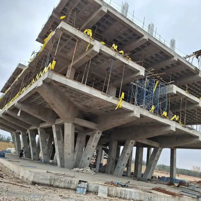
As a consequence, shear failures demand heightened attention from structural engineers, particularly when designing structures where mitigating the risk of abrupt shear collapse is paramount, such as transfer structures or structures subjected to high shear load.
The shear response of reinforced concrete beams exhibits significant complexity and is influenced by a lot of parameters. These factors include, but are not limited to, the ratio of shear span to depth, the percentage of longitudinal reinforcement, the overall member depth, the width of existing cracks, and the presence or absence of transverse reinforcement (stirrups or links).
Due to this inherent complexity, a universally accepted and straightforward theory for predicting shear behaviour is yet to be established. Consequently, a number of international concrete design codes continue to employ empirically derived shear design methodologies.
Shear failure usually occurs in the form of diagonal cracks and must be checked under the ultimate limit state during the structural design of buildings. In reinforced concrete buildings, shear is resisted using links (stirrups). When a design is failing in shear, the following solutions can be adopted;
(1) Increasing the depth of the beam
(2) Increasing the width of the beam
(3) Increasing the area of shear reinforcement provided and/or reducing the spacing of the links.
It is not very common to modify the percentage of longitudinal reinforcement for the purpose of shear resistance.
High Shear Load Resistance According to EC2
Eurocode 2 employs the strut-and-tie model to represent the shear resistance mechanism. In this model, the shear force is resisted by:
- Concrete compression strut: This imaginary strut, inclined at an angle with respect to the beam axis, transmits compressive forces. The angle varies between 21.8 degrees to 45 degrees.
- Transverse reinforcement: Stirrups or links provide tensile resistance to prevent the formation and propagation of diagonal cracks.
When the design shear force VEd exceeds the design shear resistance of the concrete section alone (VRd,c), then a shear reinforcement design is required. The design involves providing the spacing and area of stirrups to resist the difference (VEd – VRd,c). Eurocode 2 provides design equations for calculating the required shear reinforcement area (Asw) based on the design shear force, material properties, and inclination of the concrete strut (θ). The code provides limitations on the angle of the concrete strut and the maximum shear force a section can resist.
The maximum allowable strut angle is 45 degrees (cot θ = 1.0). When the strut angle exceeds 45 degrees, a new section will have to be selected. Where necessary, especially under high shear loads, it is important to determine the intermediate (actual) strut angle which depends on the applied shear stress.
Design Example for High Shear Load

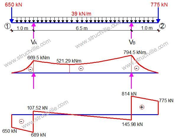
In this article, a beam is loaded at the ultimate limit state as shown above. We are to design support B for shear according to Eurocode 2 and BS 8110. The preliminary design data is given below.
Design Data:
Concrete Strength = 25 N/mm2
Grade of steel = 500 N/mm2
Width of beam = 300 mm
Depth of beam = 750 mm
Concrete cover = 35 mm
FLEXURAL DESIGN OF SUPPORT B
MEd = 794.5 kN.m
Effective depth (d) = h – Cnom – ϕ/2 – ϕlinks
Assuming ϕ25 mm bars will be employed for the main bars, and ϕ10 mm bars for the stirrups (links)
d = 750 – 35 – (25/2) – 10 = 693 mm
k = MEd/(fckbd2) = (794.5 × 10⁶)/(25 × 300 × 6932) = 0.220
Since k > 0.167, compression reinforcement required
Area of compression reinforcement AS2 = (MEd – MRd) / (0.87fyk (d – d2))
MRd = 0.167fckbd2 = (0.167 × 25 × 300 × 6932) × 10-6 = 602 kNm
d2 = 35 + 12.5 + 10 = 57.5 mm
AS2 = ((794.5 – 602) × 106) / (0.87 × 460 × (693 – 57.5)) = 757 mm2
Provide 4H16 Bottom (Asprov = 804 mm2)
Area of tension reinforcement As1 = MRd / (0.87fyk z) + AS2
Where z = d[0.5+ √(0.25 – 0.882k’)]
k’ = 0.167
z = d[0.5+ √((0.25 – 0.882(0.167))] = 0.82d
As1 = MRd / (0.87fyk z) + AS2 = ( 602 × 106) / (0.87 × 500 × 0.82 × 693) + 757 mm2 = 3192 mm2
Provide 7H25 TOP (ASprov = 3437 mm2)
SHEAR DESIGN ACCORDING EC2
Support B;
VEd = 814 kN
VRd,c = [CRd,c.k.(100ρ1 fck)(1/3) + k1.σcp]bw.d ≥ (Vmin + k1.σcp) bw.d
CRd,c = 0.18/γc = 0.18/1.5 = 0.12
k = 1 + √(200/d) = 1 + √(200/693) = 1.53 < 2.0, therefore, k = 1.53
Vmin = 0.035k(3/2) fck0.5
Vmin = 0.035 × (1.53)1.5 × 250.5 = 0.27 N/mm2
ρ1 = As/bd = 3437/(300 × 693) = 0.0165 < 0.02; Therefore take 0.0165
VRd,c = [0.12 × 1.53 (100 × 0.0165 × 25 )(1/3)] × 300 × 693 = 131887 N = 132 kN
Since VRd,c (132 kN) < VEd (814 kN), shear reinforcement is required.
The compression capacity of the compression strut (VRd,max) assuming θ = 21.8° (cot θ = 2.5)
VRd,max = (bw.z.v1.fcd) / (cotθ + tanθ)
V1 = 0.6(1 – fck/250) = 0.6(1 – 25/250) = 0.54
fcd = (αcc fck) / γc = (0.85 × 25) / 1.5 = 14.167 N/mm2
Let z = 0.9d
VRd,max = [(300 × 0.9 × 693 × 0.54 × 14.167) / (2.5 + 0.4)] × 10-3 = 565 kN
Since VRd,c < VRd,max < VEd
We need to modify the strut angle
θ = 0.5sin-1[(VRd,max /bwd)/0.153fck(1 – fck/250)]
θ = 0.5sin-1[(565000/(300 × 693))/3.4425] = 26°
Since θ < 45°, the section is okay for the applied shear stress
Hence Asw / S = VEd / (0.87 fyk z cot θ) = 814000 / (0.87 × 500 × 0.9 × 693 × 2.05 ) = 1.463
Minimum shear reinforcement;
Asw / S = ρw,min × bw × sinα (α = 90° for vertical links)
ρw,min = (0.08 × √(fck)) / fyk = (0.08 × √25) / 500 = 0.0008
Asw/Smin = 0.0008 × 300 × 1 = 0.24
Maximum spacing of shear links = 0.75d = 0.75 × 693 = 520 mm
Provide H10mm @ 100 mm c/c as shear links (Asw/S = 1.57) Ok!!!!
As a means of comparison, let us consider the shear design of the same support according to BS 8110, assuming the same area of tension reinforcement was provided.
SHEAR DESIGN BY BS 8110-1:1997
Design of support B
Ultimate shear force at the centerline of support
V = 814 kN
Using the shear force at the centreline of support;
Shear stress v = V/(bd ) = (814 × 103) / (300 × 693) = 3.915 N/mm2
v (3.915 N/mm2 ) < 0.8√fcu (4.00 N/mm2 ). Hence, the dimensions of the cross-section are adequate for shear.
Concrete resistance shear stress
vc = 0.632 × (100As/bd)1/3 (400/d)1/4
(100As/bd) = (100 × 3437) / (300 × 693) = 1.653 < 3.0 (See Table 3.8 BS 8110-1;1997)
(400/d)1/4 = (400/693)1/4 = 0.87; But for members with shear reinforcement, this value should not be less than 1. Therefore take the value as 1.0
vc = 0.632 × (1.653)1/3 × 1.0 = 0.747 N/mm2
Let us check;
(vc + 0.4)1.147 N/mm2 < v(3.915 N/mm2) < 0.8√fck (4.00 N/mm2)
Therefore, provide shear reinforcement links.
Let us try 2 legs of T10mm bars (Area of steel provided = 157 mm2)
Asv/Sv = [bv (v – vc)]/(0.87 × fyv) = [300 × (3.915 – 0.747)] / (0.87 × 500) = 2.184
Maximum spacing = 0.75d = 0.75 × 693 = 520 mm
Try 3 legs of T10mm
Provide 3 legs Y10mm @ 100 mm c/c links as shear reinforcement (Asv/Sv = 2.34)
We can therefore see that disregarding load factor and flexural design requirements, EC2 is more economical than BS 8110 in shear design, and in this case study by about 33%.


You said, (bv(v-vc))/0.95fyv. but u used 0.87fyv why?
And please I wud like u to break it down fr me the reason fr 3 legs I am a bit confused.
Thank u very much.
Dear Ovie,
The 0.95 and 0.87 was an oversight which has been corrected. I used 0.87Fy because the design was done with Class C reinforcement, with yield strength of 500 Mpa.
On the other hand, you know links are usually bent into rectangular shape with two legs on each side when installed in beams. This time around, we are introducing one more leg in the middle to assist in shear resistance. Thanks.
• Thanks for helping us understand this topic. You have written it in a way that makes it very simple to understand. Thank you so much. BIM Consulting
BIM Solutions
BIM Solutions in UK
Shop Drawings Preparation in UK