The internet space (mostly blogs) is filled with so much information about hidden beams (also called concealed beams) which is defined as a beam whose depth is equal to the thickness of the slab. In other words, the beam is embedded inside/within the reinforced concrete slab. However, in standard civil engineering textbooks, codes, and standards, no mention is usually made of hidden beams. On a very simple explanation, the idea of hidden beams is the provision of more reinforcements with shear stirrups in a banded area of a floor slab.
According to the literature review of a 2020 research carried out in Ankara, Turkey, and published by the Journal of Building Engineering (Elsevier) no previous literature on experimental studies on hidden beams was encountered by the authors. By implication, prior to the year 2020, no experimental studies have been published on the behaviour of hidden beams.
On the issue of hidden beams, the researchers (Özbek et al., 2020) said,
… some of the designers illegally try to remove the beams by arranging the reinforcement with equivalent strength in the slab and call it the hidden beam. In other words, these hidden beams are constructed by placing additional longitudinal reinforcing bars in the slab along the line where the actual beam should have been present.

In the research by Özbek et al., (2020), reinforcement ratio and slab thickness were used as the test parameters for the 14 specimens used in the pioneering research campaign. The results showed that hidden beams were able to achieve reference strength of equivalent drop beams after excessive deformations (about eight times larger) or in some cases never achieved the reference strength.
A construction concept that comes close to the so-called hidden beams is the idea of a wide-shallow beam or wide-band beams. A wide-shallow beam is a beam whose depth is generally lower than 350 mm with a cross-section having the width over the depth ratio greater than 2. However, the commonly used values in practice are 250–300 mm for depth and 4–5 for the width to depth ratio (Özbek et al., 2020). Wide-shallow beams are usually adopted in the construction of one-way ribbed slabs and maintain the same thickness with the slab for architectural convenience and for supporting partition loads.
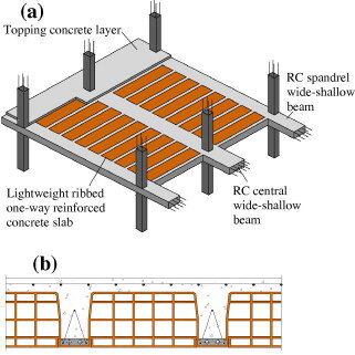
In a numerical modelling study published in the Asian Journal of Engineering and Technology by Mohd and Helou (2014) titled ‘Slabs with hidden beams: facts and fallacies‘, the authors concluded that in comparison with the system of drop beams, selected as a comparison basis, hidden beams provide little, if any, added value. Moreover, under monostatic loading, the hidden beams behave more of a slab than a beam.
Furthermore, Helou and Awad (2014) suggested that the presence of hidden can add to the vulnerability of the supporting columns under seismic conditions since they tend to be significantly stiffer than the columns thereby contradicting the preferred strong column-weak beam arrangement.
Numerical Modelling of Hidden Beams
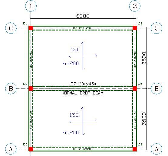
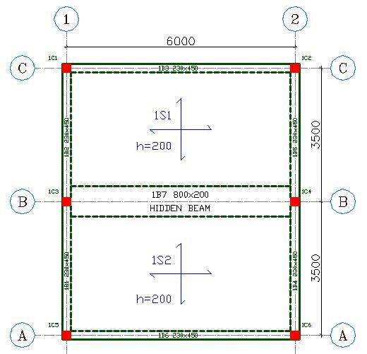
To investigate the design concept of a typical hidden beam, a simple numerical model was carried out using design software, Prota Structures. A simply supported slab of dimensions 7m x 6m and thickness of 200 mm was modelled under the following conditions;
(a) A solid slab without internal beams (CASE 1)
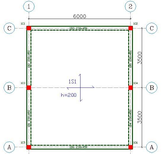
(b) A solid slab with a drop beam (450 x 230 mm) at the midspan (CASE 2)
(c) A solid slab with a beam of 200 mm depth and width of 800 mm at the midspan (hidden beam) – CASE 3
Design data
fck = 25 MPa
fyk = 460 Mpa
Concrete cover = 25 mm
Imposed/live/variable action (load) = 3 kN/m2
Additional dead/permanent action (finishes) = 1.5 kN/m2
Analysis Results
Case 1
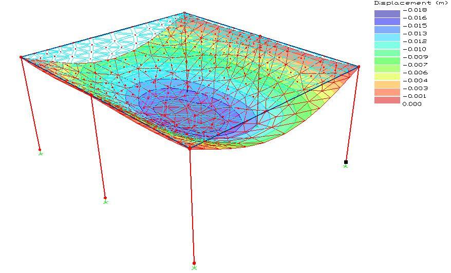
From the analysis and design of the floor system as a solid slab without any internal beam, the maximum elastic deflection under the reference load was observed to be 18 mm. For the design, the use of T12@100 c/c (parallel to the short span) was observed to satisfy strength and deflection requirements with allowable span/effective depth ratio of 37.98 and actual span/effective depth ratio of 35.503.
Case 2
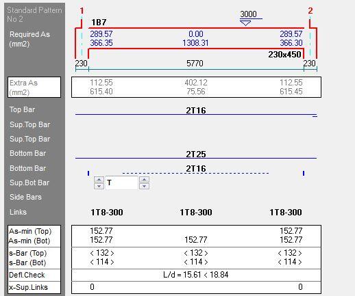
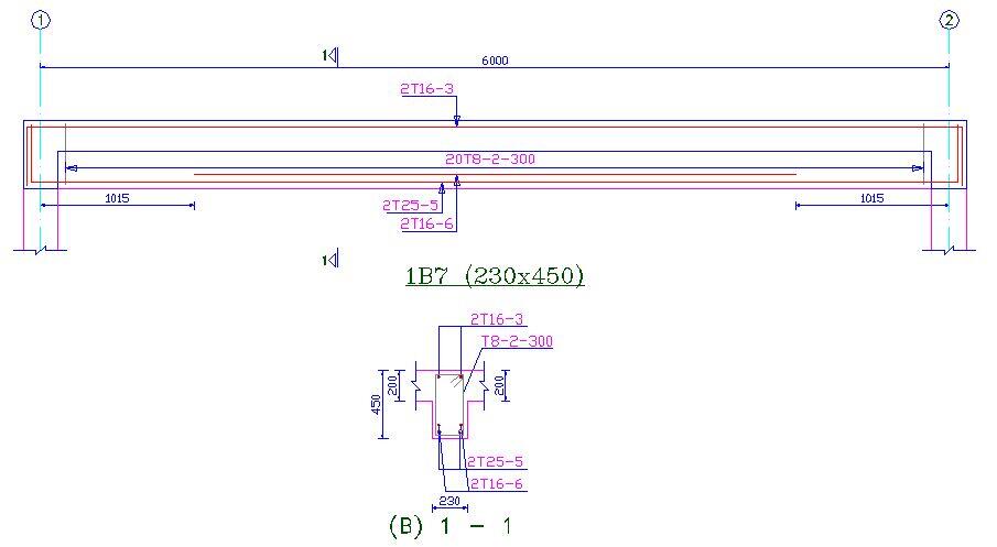
For the slab with a normal drop beam of 450 x 230 mm at the mid-span, the following analysis and design results were obtained for the normal drop beam. At the bottom of the beam (tension zone), the area of steel required was 1308 mm2, while the area of steel provided was 1384 mm2 (2T25 + 2T16). The allowable span/effective depth ratio was calculated as 18.84 while the actual span/effective depth ratio was calculated as 15.61. By implication, the design requirements were observed to be satisfied as shown in Figure 7. The reinforcement detailing is shown in Figure 8.
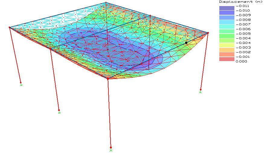
The elastic deflection of the slab under the reference load and arrangement (drop beam at the mid-span) as shown in Figure 9 was observed to be 11 mm;
Case 3
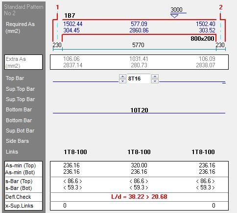
For a slab with a hidden beam of 200 x 800 mm, the following analysis and design results were obtained for the hidden beam. The area of tension reinforcement required was calculated as 2861 mm2, while the area of compression reinforcement required was calculated as 577 mm2. The area of steel provided in the tension zone was 3140 mm2 (10T20), while the area of steel provided in the compression zone was 1608 mm2 (8T16).
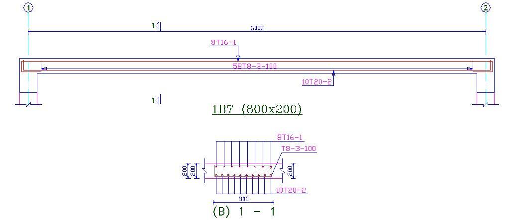
Furthermore, unusually high reinforcement requirement was observed at the supports of the hidden beam. The allowable span/effective depth ratio was calculated as 20.68 while the actual span/effective depth ratio was calculated as 38.22. By implication, despite the heavy reinforcement provided in the band of the hidden beam, it failed in deflection using ‘deemed to satisfy rules’ as shown in Figure 10. The reinforcement detailing is shown in Figure 11.
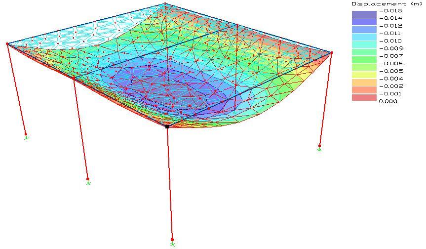
The deflection of the slab under the reference load and hidden beam arrangement as shown in the Figure 12 was observed to be as 15 mm.
Conclusion
From the literature surveyed and from the simple numerical model carried out in this study, the use of hidden beams do not appear to be favourable or significantly beneficial to the behaviour of floor slabs. In other words, the parameter that significantly affects the deflection behaviour of slabs which is the depth will effectively remain constant, while the designer tweaks the area of steel for higher modification factor. In other words, the design of hidden beams can only be based on strength and not deformation.
A lot of blogs suggest that hidden beams are designed as normal beams, with the sole difference of having the same depth with the slab. However, a little study of the hidden beam designed in CASE 3 showed that it failed in deflection and will not likely pass no matter how how the reinforcement is tweaked. By implication, if the hidden beam is assumed as a regular support and the slab designed as two panels as in CASE 2 (lx = 3500 mm), the slab will still likely have serious problems with deflection, unless the satisfactory Y12@100 c/c steel or equivalent area provided in the slab. This therefore makes no economical sense.
Therefore, the use of hidden beams in floor slabs appears to be an imaginary strength enhancing concept without any research based technical backing so far.
References
[1] Conforti A., Minelli F., Plizzari G. A. (2013): Wide-shallow beams with and without steel fibres: A peculiar behaviour in shear and flexure. Composites Part B: Engineering (51):282-290 https://doi.org/10.1016/j.compositesb.2013.03.033
[2] Helou S. H. and Awad R. (2014): Performance-based analysis of hidden beams in reinforced concrete structures. MATEC Web of Conferences (16)100001 (2014)
[3] Mohd M. and Helou S. (2014): Slabs with Hidden Beams, Facts and Fallacies. Asian Journal of Engineering and Technology 02(04):316-319
[4] Özbek E., Aykaç B., Bocek M., Cem Yılmaz M. C., Mohammed A. B. K., Er S. B., Aykaç S. (2020): Behavior and strength of hidden Rc beams embedded in slabs. Journal of Building Engineering, 29(2):101130. https://doi.org/10.1016/j.jobe.2019.101130





Hello Obinna,
For the Case 3, hidden beam, what was the reinforcement required to satisfy deflection requirements for the slab?
Depth is the critical issue in case 3. No reinforcement manipulation can satisfy the deflection.
Concealed beams are useful to control long term deflections due to creep.
Well done Obinna,
This is what I usually tell people. The use of hidden beams is even tantermous to wastage of rebar which will eventually causing more harm to the structure. Unless it is deeper to pass deflection or in another words in rib slabs.
Thanks.
This is the case that is being practised by many site supervisors on site without actually knowing that the concealed beam plays no significant effect in the slab.
I have experienced things like this in design but what I realized is that when I make the concealed beam wider it tend to assistant to improve deflection. But the implication is that the slab width reduces with an increase in beam width. Hence a reduction in load being transferred to the concealed beam from the slab as the slab section is reduced.
In all it is uneconomical because of the reinforcements that will be required in the beam.
Good writeup Obinna.
From case 2, I believe it should satisfy deflection requirements for the slab more than case 1. Just that the mid-span beam will mobilize more reinforcement than the edge.
Your analysis is based on only calculation but not on the behavioural pattern of the slab under imposed/ dead load.correct me if I’m wrong
Thank you Engr Obinna. please how can i get a copy of this. i will like to even have a discussion with you concerning this. i am a masters student trying round up the programme by doing my thesis on conceal beams.
Another example of hidden beams often encountered are concrete tilt-up wall panels. Cast horizontal than tilted into a vertical position, the vertical concrete wall panel area between window openings is usually designed as a vertical beam with the same depth of the adjacent concrete panel areas having additional flexural and shear reinforcement.
The research has given me indepth knowledge as far far as civil engineering is concerned.
Thanks, engineer Ubina
the design cases are with the solid slabs..i would love to dig deeper in the purpose of theses concealed/hidden beams in a ribbed slab panels..