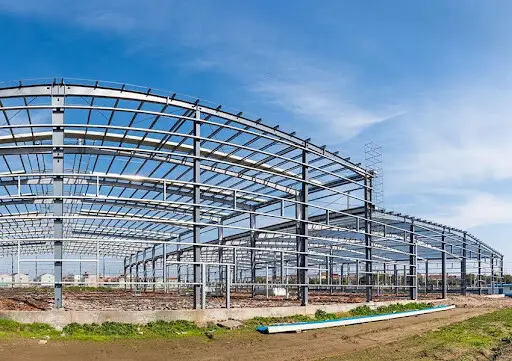
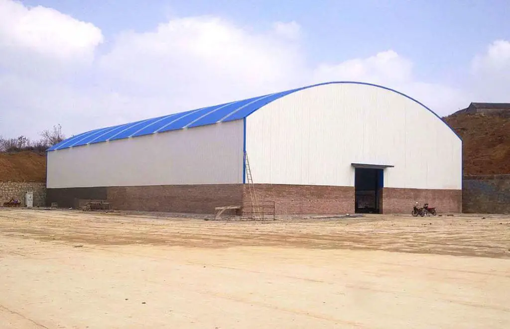
Curved rafters can be adopted in the construction of industrial buildings, warehouses, churches, etc due to their aesthetic appeal. Quite a significant number of portal frames have been constructed all over the world with curved rafters. The relative simplicity of construction can also be a reason for the adoption of curved rafters given that the need for ridge details in the sheeting will be eliminated. Universal Beams are commonly used for curved rafters.
The curving process for a rafter can be achieved using the roller bending or induction bending process, with the former being more popular than the latter due to the cost implications. A straight portion always remains at the end of each bar after curving a member. If a perfectly curved rafter is required, then the straight lengths at the ends should be cut off.
However, for economical reasons, the straight portions can be included to form the final length of the member. This eliminates off-cut waste and the need for making additional cuts. In practical construction, it is difficult to observe the effect of curvature at the end of rafters, therefore it is acceptable to retain the straight portions at the ends. This can also simplify the fabrication of the haunches.
Design Issues of Curved Rafters
Discussed in the sections below are some of the issues encountered in the design of curved rafters;
Residual Stresses
It is important to know that the process of curving steel members affects the residual stresses in the member. The magnitude of residual stresses remaining after the curving process depends on the section properties in the plane of curvature. Residual stresses do not affect the cross-sectional resistance of a section.
For Universal Beams curved in elevation (such as curved rafters), the ratio Sx/Zx is typically 1.12. Therefore;
pr = (1.12 – 1)py = 0.12py
This level of residual stress is well within the range commonly found in straight beams due to the differential rate of cooling at the mills between the web and the flange tip. Because the curving process induces strains in excess of the yield strain, the curving process will remove the residual stresses from the straight beam. The residual stresses will therefore be limited to those caused by the curving process, and are not in addition to those in a straight beam.
Out-of-plane bending of flanges due to curvature
The flanges of curved rafters subject to in-plane bending or axial loads must also resist the out-of-plane component of loads resulting from the curvature of the member. This applies to both open sections and box sections.
The out-of-plane bending stress of an I-section is given by;
σ2 = 3σ1b2/RT
Frame analysis – elastic or plastic?
According to King and Brown (2001), elastic frame analysis may be used for any frame with members curved in elevation, provided that the geometry of the curved elements is allowed for. The member resistance checks for structures designed elastically. Plastic analysis is common for portal frames with straight members, and may also be used, within limits, to analyse portal frames with curved rafters.
Modelling curved members for analysis
Computer software can normally only model straight lengths of elements. It is possible to use a series of short straight segments to model a curved member but there are several issues that should be considered. The accuracy of the model will improve with the number of analysis elements, provided that these are chosen so that the off-set between the curved member and the segments is minimised.
The choice of the number of elements will depend largely on the curvature of each curved member. For members with a very slight curvature, there is normally no need to divide the model into a large number of analysis elements, as the differences between the analysis model and the actual structure can be accounted for simply.
Procedure for the design of curved rafters
In common with all portal frames, the following steps must be followed:
· determination of initial sizes
· check of in-plane stability
· check of member resistances
To show how this can be done, a solved example is presented below. The design procedure and geometry are similar to the same presented by King and Brown (2001) using BS 5950-1:2000 design code.
Initial sizes
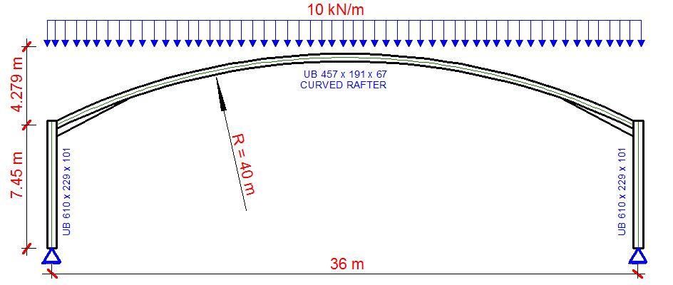
Following an initial analysis, the members shown in the general arrangement below were chosen. The purlins are spaced at 1.5m centre to centre.
Section Properties
Rafters – 457 x 191 x 67 UB S275
D = 453.4mm; B =189.9 mm; t = 8.5 mm; T = 12.7mm; r = 10.2 mm; A = 85.5 cm2; J = 31.1 cm4; Zx = 153 cm3; Zy =153 cm3; Sx = 1470 cm3; Iy = 1450 cm4; ry = 4.12 cm; rx = 18.5 cm; H = 0.705 dm6
In-plane stability
The portal geometry must be checked to ensure the (simple) sway-check method may be used to verify that the portal is stable in-plane.
5 × h = 5 × 7.450 = 37.25 m
span, L = 36 m < 37.25 m Okay
Rise hr = 4.279 m (based on centre-line dimensions)
0.25 × span = 0.25 × 36 = 9 m > 4.25 m Okay
The sway-check method may therefore be used. The notional horizontal loads are taken as 0.5% of the base reaction and applied horizontally in the same direction at the top of each column. The modelling has been carried out using Staad Pro software with 36 straight members to form the curved rafters as shown below.
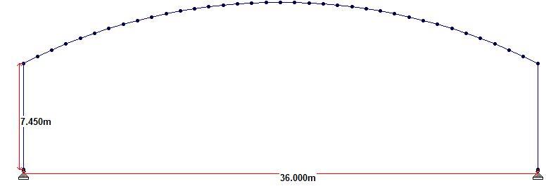
With a uniformly distributed ultimate limit state load of 10 kN/m, a vertical reaction of 180 kN was obtained at both supports. The horizontal notional load applied at the top of each column was calculated as (0.005 × 180 = 0.9 kN).
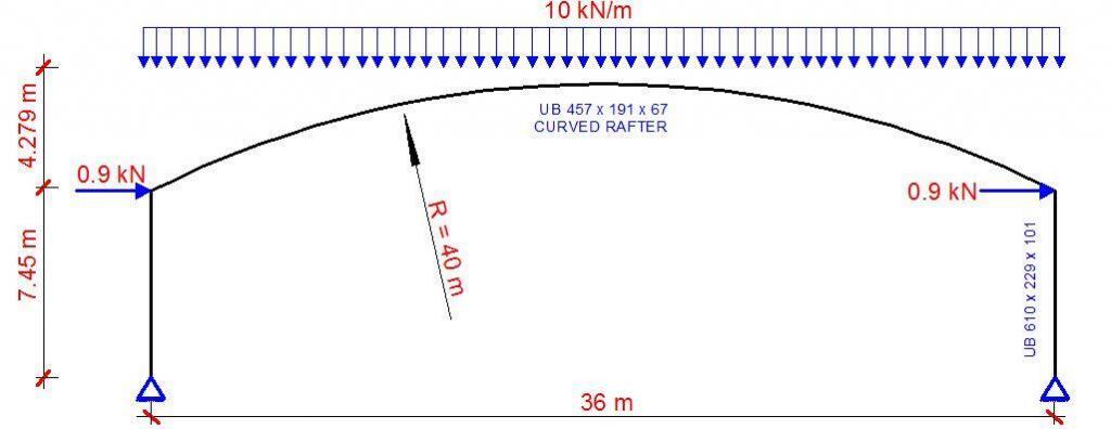
The checks on the columns are no different from those in portal frames with all straight members, and are not included in this example. Between A—B, and C-D, the curved rafter is in hogging. The bending moment produces compression on the concave side of member, and the design resistance is at least that of a straight member.
The regions A-B and C-D should be checked as if straight, with full consideration of restraint positions etc. Between points B and C, the curved rafter is sagging. The bending moment produces compression on the convex side of the member, reducing its capacity. The following checks illustrate how the member in this zone should be checked.
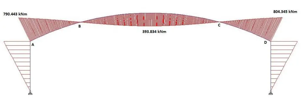
From the analysis, the maximum forces between B and C (assumed to coexist).
Where:
MEd = 393.834 kNm
NEd = 128 kN
VEd = 73.2 kN
Reduced Design Strength
The curvature of the rafter induces bending stresses in the flanges, which combine with the axial stress to reduce the effective yield stress of the section. The reduced design strength, Pyd, is calculated following the procedure given in Section 6.3.2 of King and Brown (2001):
Calculate the out-of-plane bending stress:
σ2 = 3σ1b2/RT
σ1 = MEd/Zx + NEd/A = [(393.834 × 10⁶)/(1300 × 103) + (128 × 103)/(85.5 × 103)] = 304.446 N/mm2
b = 0.5(B – t -2r) = 0.5(189.9 – 8.5 – 2 × 10.2) = 80.5 mm
σ2 = 3σ1b2/RT = (3 × 304.446 × 80.52)/(40 x 1000 × 12.7) = 11.65 N/mm2
The reduced design strength can then be calculated using the equation below;
pyd = [py2 – 3(σ2/2)2 – 3τ2]0.5 – (σ2/2)
Ignoring the shear stress τ
pyd = [2752 – 3(11.65/2)2]0.5 – (11.65/2) = 268.989 N/mm2
Cross-section capacity
This is calculated in accordance with BS 5950—1 Clause 4.8.3.2 but substituting Pyd for py
The relationship to be satisfied is:
NEd/Agpyd + MEd,x/Mcx + MEd,y/Mcy ≤ 1.0
(128 × 103)/(85.5 × 103 × 269) + (393.834 × 10⁶)/(1470 × 103 × 269) + 0 = 1.000 (Okay)
Lateral-torsional buckling
Lateral-torsional buckling between purlin positions must be checked, because the bending moment produces compression on the convex side of the member, and the resistance of the member is reduced.
Calculate effective slenderness
λLT = √(McxπE)/(MEpyd)

a = EIy = 205 × 103 × 1450 × 104 = 2.97 × 10¹² Nmm2
b = GJ + (π2EH/L2)
Assuing the purlins are spaced at 1.5 m centre to centre
b = [(205 × 103 × 37.1 × 104)/2(1 + 0.3)] + (π2 × 205 × 103 × 0.705 × 1012)/15002 = 6.3395 × 10¹¹ Nmm2
c = a + b = 2.97 × 10¹² + 6.3395 × 1011 = 3.603957 × 10¹² Nmm2
ME = [-90098941.71 + √ (90098941.712 + 3.3031385 × 10¹⁹]/2 = 2828950478 Nmm =2828.95 kNm
λLT = √(McxπE)/(MEpyd) = √(1470 × 103 × 269 × π2 × 205 × 103 )/( 2828950478 × 269) = 32.42
Lateral torsional buckling resistance
To check lateral-torsional buckling, Clause 5.5.2 directs the designer to Clause 4.8.3.3. In-plane stability has already been checked by the sway stability provisions (Clause 5.5.4) so, in general, only the second relationship (covering out-of-plane effects) needs to be satisfied.
For out-of-plane buckling:
NEd/PcY + mLTMLT/Mb ≤ 1.0
For Pcx , Le (eaves to apex) = 18.5 m approximately. Assuming a straight member without haunches:
λy = L/ry = 1500/41.2 = 36.4; pcy = 250 N/mm2
AgPcy = 8550 × 250 × 10-3 = 2137.5 kN
Over a length between purlins, the moment will be taken as constant, therefore, mLT = 1.0
with λLT = 32.42, and py = 275 N/mm2
pb = 274 N/mm2
Mb = pbSx = 274 × 1470 × 10–3 = 402.78 kNm
NEd/Pcy + mLTMLT/Mb = (128)/(2137.5) + (1.0 × 393.834)/( 402.78 ) = 1.037 > 1.00
The section is at limiting equilibrium between B and C and may be accepted for ULS or a slightly higher section selected. Rafter sections A–B and C–D, and the columns, must be checked as straight members.
References
King C. and Brown D. (2001): Design of curved steel. The Steel Construction Institute, UK

