Earth retaining structures are subjected to a myriad of loads such as earth pressure, water pressure, and earthquake loads (in seismic zones). However, when loads are applied on the earth retained at the back of the retaining wall, surcharge loads are induced on the retaining structure. The magnitude of lateral pressure transferred to the wall depends on the spatial distribution of the load, its magnitude, and location (distance away from the wall). The aim of this article is to evaluate the common sources of surcharge loads on earth retaining structures.
Different forces or loads can be placed on the earth being retained. These loads will produce a surcharge on the retaining structure. Surcharge loads on retaining walls can be permanent or temporary. The most common sources of surcharge are;
- Foundations of structures close to the retaining wall
- Pavements or compound floorings
- Moving vehicles (traffic)
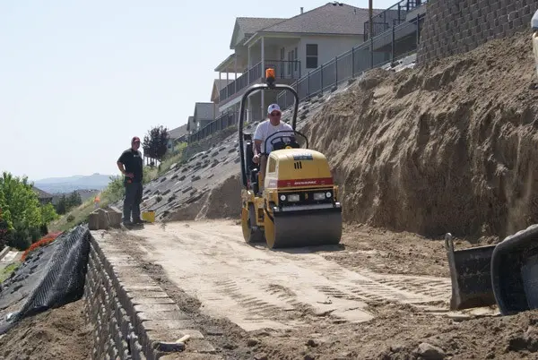
- Construction equipment
- Compaction process
- Variation in ground surfacing/undulations
These loads vary in spatial distribution and will exert different magnitudes and distributions of lateral pressure. For instance, the surcharge pressure exerted by a uniformly distributed concrete flooring will be quite different from the surcharge load due to an isolated footing close to the retaining wall. Let us now review these possible loads/actions in detail;
General Loading Condition
According to BS 8002, the minimum surcharge load that should be applied to retaining walls is 10 kN/m2. For shallower retaining walls, the surcharge may be reduced if the designer is confident that a surcharge of 10 kN/m2 will not occur during the life of the structure.
Additional surcharge loading should be used in the design to take account of incidental loading arising from the construction plant, stacking of materials, and movement of traffic both during construction and subsequently unless the nature or layout of the site precludes the need for such additional surcharge. However, as practicable as possible, stockpiling materials close to retaining walls should be avoided.
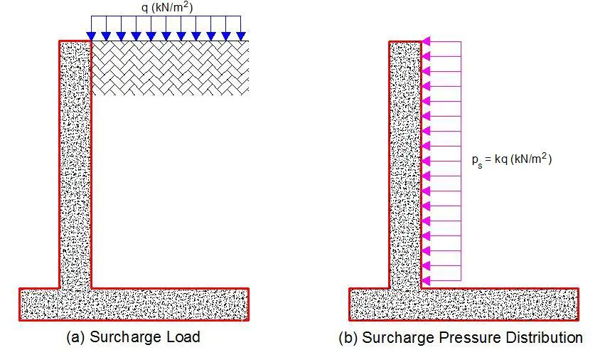
Uniform surcharge loads such as that due to HA load and 45 units of HB loads (with values of10 kN/m2 and 20 kN/m2 respectively) will exert a rectangular pressure distribution on the back of the retaining wall. The magnitude of the surcharge pressure (ps) will be given by;
ps = khq (kN/m2)
Where;
kh = coefficient of active earth pressure or at rest (as appropriate)
ka = coefficient of active pressure = (1 – sin Φ’)/ (1 + sin Φ’)
k0 = coefficient of earth pressure at rest = 1 – sin Φ’
q = characteristic value of the surcharge load (kN/m2)
Imposed Surcharge Loads from Traffic: Highways
Where retaining walls give support to highways it was traditional to check for the effects of HA loading at ground level. HA surcharge load is usually taken to be 10 kN/m2. According to BD37/01, the surcharge load for 45 units of HB load should be 20 kN/m2. The equivalent to BS EN 1991-2 and the UK NA is the application of the load model in Figure NA.6 of the National Annex, where the axle loads are 65, 65, 115, and 75 kN (S = 320 kN) at centres 1.2, 3.9 and 1.3 m apart (S = 6.4 m) as shown in Figure 2. Each axle consists of two wheels of equal load at a distance of 2.0 m apart.
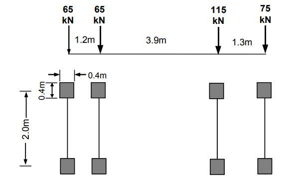
Clause 6.6.3 of PD 6694-1 allows an alternative. For global effects on ‘other earth retaining walls’ adjacent to highways, two vertical uniformly distributed transverse line loads of QL, are applied 2.0 m apart on a notional lane of the carriageway, where
QL = 320/(2 × 6.4) = 25 kN/m over a length of 6.4 m
Besides normal γQ factors, axle loads and line loads are subject to an overload factor of 1.5 and, when checking a single vehicle in one notional lane, a dynamic factor of 1.4. The dynamic factor dissipates to 1.0 at 7.0 m depth or when convoys of vehicles are considered in each notional lane (representing a traffic jam situation).
In association with the axle loads or line loads, it is suggested that a surcharge of 5 kN/m2 is applied as an imposed load to pavements adjacent to basements. This figure is in agreement with NA.2.36 of the UK NA to BS EN 1991-2 as a maximum uniformly distributed load for continuous dense crowding (e.g. footbridges serving a stadium) and with BS EN 1991-1-1 for traffic and parking areas with vehicles > 30 kN.
Concentrated Surcharge Loads (Point Loads)
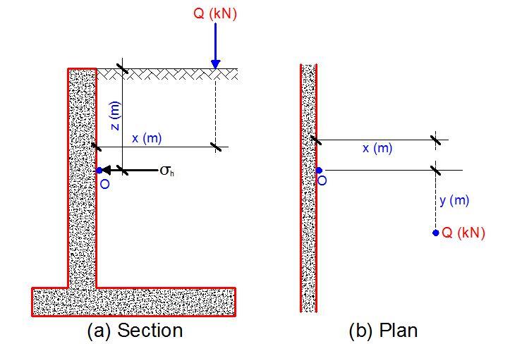
Using Boussinesq equations to determine vertical pressure, lateral pressure at a point O on a wall due to a discrete load Q as shown in Figure 3 may be taken as:
σ’ah = Kh(3QZ3)/(2πR5)
where
Kh = Kad or K0d (coefficient of active pressure or at rest as appropriate)
Q = load, kN
Z = depth, m
R = (x2 + y2 + z2)0.5
It is recommended that horizontal earth pressures against ‘rigid’ walls determined using Boussinesq’s theory of stresses in an elastic half-space should be doubled for design purposes. Boussinesq’s theory for horizontal pressures assumes horizontal movement. However, with truly rigid walls there is actually no movement. So an identical balancing surcharge on the other side of the wall, i.e. a mirror image surcharge, is required and this in effect doubles the pressure. Doubling pressure is in line with field data by Terzarghi and with French practice.
Surcharge Line Load Parallel to Retaining Wall
Assuming that the length of the load is comparable to that of the wall, lateral pressure at a point O will depend mainly on the depth z. In this case, lateral pressure may be taken as:
σ’ah = Kh(2QZ3)/(πR4)
where
Kh = Kad or K0d as appropriate
Q = load per metre length of load kN/m
Z = depth, m
R = (x2 + z2)0.5
As explained earlier, it is recommended that horizontal earth pressures determined using Boussinesq’s theory of stresses in an elastic half-space should be doubled.
Strip Surcharge Load Parallel to Retaining Wall
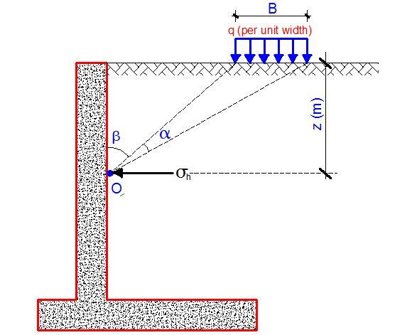
Assuming that the length of the load is comparable to that of the wall, lateral pressure at a point O will depend only on the depth z as shown in Figure 4. In this case, lateral pressure may be taken as:
σ’ah = Kh(q/π) [α + sinα cos(α + 2β)]
where
Kh = Kad or K0d as appropriate
q = load per metre width of load
α, β = angles (in radians)
Rectangular Surcharge Loads Exerting Uniform Pressure
Rectangular loads such as pad footings will exert a surcharge load on retaining walls. Standard textbooks provide solutions for vertical stress, σ’v,z at depth z under a corner of a rectangular area carrying a uniform pressure q. It is usually in the form;
σ’v,z = qIr
where;
q = uniform pressure
Ir = coefficient.
Values of Ir are provided for different aspect ratios of the loaded area to depth and can be read from Fadum’s chart. Lateral pressure at the required depth may be determined as KhqIr. The method of superposition allows the determination of vertical stress under any point within or outside the loaded area. An example of this has been presented on how to apply surcharge load from pad footings to retaining walls.
Compaction Pressure on Retaining Walls
The lateral pressure due to the action of compacting equipment can induce surcharge load on the earth retaining structure. The magnitude of the lateral pressure depends on the characteristic design compaction design force, the unit weight of the soil, and the coefficient of earth pressure adopted. The compaction pressure of machines on earth retaining walls can be read here.

