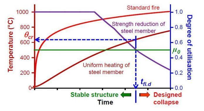
The action of fire on a structure is represented by thermal actions, and EN 1991-1-2:2002 (Eurocode 1, Part 2) provides several options for considering thermal action on steel structures. Time-temperature relationships are one of the numerous ways of representing fire actions on structures. These are relationships that show the evolution of a temperature that represents the environment around the structure as a function of time. The heat flux transported from the environment to the structure can be calculated using this temperature and the relevant boundary conditions.
Relationships that directly give the heat flux impinging on the structure are another option. The temperature evolution in the structure is then determined by combining the impinging heat flux with the flux emitted by the structure. Eurocode 1 distinguishes between nominal temperature-time curves, which include the standard temperature-time curve, the hydrocarbon curve, the external fire curve, and on the other hand, the natural fire models. The thermal action to be employed is usually a legal requirement set by the country or region in which the structure is located, and it is determined by the building’s size, usage, and occupancy (Franssen and Real, 2015).
Some countries impose prescriptive standards that specify the time-temperature curve as well as the time (referred to as fire resistance) that the structure must withstand when subjected to this curve. For example, a hotel in Country A must have a 60-minute resistance to the standard curve, whereas a railway station in country B must have a 30-minute resistance to the hydrocarbon curve. In such circumstances, the designer must guarantee that the construction meets the criterion and must use the time-temperature curve that has been provided (Franssen and Real, 2015).
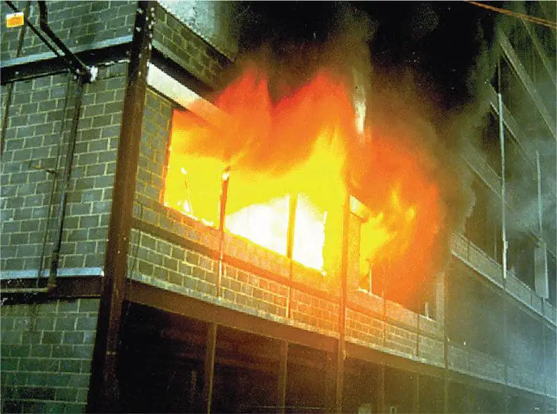
The regulation in other countries or areas may be more flexible, allowing the designer to create a performance-based design. Although the Eurocode provides some assistance in the form of restrictions of application to some of the proposed natural fire models, it is the designer’s obligation to adopt an acceptable representation of the fire in this scenario.
Such natural fire models should ideally be utilized in conjunction with performance-based requirements, such as the time required for evacuation or intervention. Before beginning any performance-based design, it is recommended to obtain consent from the authority with jurisdiction over the design fire and design scenario.
Nominal Temperature-Time Curves for Thermal Actions
Temperature-time curves are time-dependent analytical functions that yield a temperature. Because these functions are continuous, they can be used to create a curve in a time-temperature plane. Because they aren’t supposed to represent a genuine fire, they’re called nominal. They must be regarded as standard, or arbitrary, functions (Franssen and Real, 2015).
This is why the phrase “fire curve” is a misnomer because it implies that the temperature is the same as the temperature of a fire. In fact, the temperature is on par with what is found in fires. Such relationships are to be used in a prescriptive regulatory context because they are quite conventional. As a result, any requirement defined in terms of a nominal curve is both prescriptive and, in some ways, arbitrary (Franssen and Real, 2015).
The time it takes to evacuate or intervene should not be equated to the resistance of a structure to a nominal fire. Three distinct nominal temperature-time curves are proposed by Eurocode 1. The standard temperature-time curve is the one that has been used in standard fire tests to grade structural and separating elements in the past, and it is still used today. It’s used to symbolize a compartment with a fully formed fire. Because the formula was derived from the ISO 834 standard, it is commonly referred to as the ISO curve. Equation (1) gives us this standard curve;
θg = 20 + 345log10 (8t +1) ——– (1)
where θg is the gas temperature in °C and t is the time in minutes.
When a regulatory requirement is defined as Rxx, with xx equal to 30 or 60 minutes, for example, it implies that the standard fire curve must be used to evaluate the structural parts’ duration fire resistance.
The external time-temperature curve is used to describe the exterior surface of separating external walls of a building that are exposed to a fire that starts outside the building or flames that come in through the windows of a compartment below or adjacent to the external wall.
Note: This curve should not be used to calculate the effects of a fire on an exterior load-bearing structure outside the building envelope, such as steel beams and columns. Annex B of Eurocode 1 describes the thermal attack on external structural steel parts.
The external curve is given by Equation (2);
θg = 20 + 660(1− 0.687e−0.32t − 0.313e−3.8t ) ——– (2)
The hydrocarbon time-temperature curve is used for representing the effects of a hydrocarbon type fire. It is given by Equation (3);
θg = 20 + 1080 (1 − 0.325e−0.167t − 0.675e−2.5t ) ——–(3)
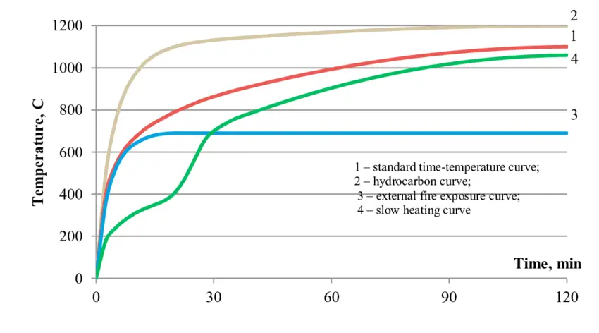
In Fig. 2, the standard and hydrocarbon curves are compared. It can be seen that the hydrocarbon curve rises rapidly and achieves a constant temperature of 1100 °C within half an hour, whereas the standard curve rises more slowly but steadily over time. Equation (4) should be used to simulate the heat flow at the surface of a steel element when the environment is represented by a gas temperature, as is the case for nominal curves.
hnet = αc(θg − θm) + Φεmεf σ[(θr + 273)4 − (θm + 273)4] ——– (4)
where;
αc is the coefficient of convection which is taken as 25 W/m²K for the standard or the external fire curve and 50 W/m²K for the hydrocarbon curve,
θg is the gas temperature in the vicinity of the surface either calculated from Eqs. (1), (2) or (3) or taken as 20 °C
θm is the surface temperature of the steel member (the evolution of which has to be calculated)
Φ is a configuration factor that is usually taken equal to 1.0 but can also be calculated using Annex G of Eurocode 1 when so-called position or shadow effects have to be taken into account
εm is the surface emissivity of the member taken as 0.7 for carbon steel, 0.4 for stainless steel, and 0.8 for other materials
εf is the emissivity of the fire, in general, taken as 1.0
σ is the Stephan Boltzmann constant equal to 5.67 × 10⁻⁸ W/m²K4
θr is the radiation temperature of the fire environment taken as equal to θg in the case of fully engulfed members.
References
Franssen J. and Paulo Vila Real P. V. (2015): Fire Design of Steel Structures (2nd Edition). ECCS – European Convention for Constructional Steelwork

