Highway bridges are subjected to a myriad of direct and indirect forces. For the purpose of obtaining the action effects on bridges, bridge designers must obtain the adequate load combination for highway bridges that will give the worst effect on any part of the bridge. The predominant action on highway bridges is gravity loads due to self-weight and the mass/dynamic effects of moving traffic. Other actions that are frequently considered are temperature loads, construction loads, snow loads, earthquake loads, and possible differential settlement of the foundation.
In this article, we are going to consider the load combinations for highway bridges according to UK standards (BD 37/01) and Eurocodes (EN 1990:2002 and EN 1991-2).
Load Combinations for Highway Bridges in the UK
In the UK, five combinations of loading are considered for the purposes of design: three principal and two secondary. These are defined in Clause 4.4 and Table 1 of BD 37/01. It is usual in practice to design for Combination 1 and to check other combinations if necessary.
Combination 1. For highway and foot/cycle track bridges, the loads to be considered are the permanent loads, together with the appropriate primary live loads, and, for railway bridges, the permanent loads, together with the appropriate primary and secondary live loads.
Combination 2. For all bridges, the loads to be considered are the loads in combination 1, together with those due to wind and, where erection is being considered, temporary erection loads.
Combination 3. For all bridges, the loads to be considered are the loads in combination 1, together with those arising from restraint due to the effects of temperature range and difference, and, where erection is being considered, temporary erection loads.
Combination 4. Combination 4 does not apply to railway bridges except for vehicle collision loading on bridge supports. For highway bridges, the loads to be considered are the permanent loads and the secondary live loads, together with the appropriate primary live loads associated with them. Secondary live loads shall be considered separately and are not required to be combined. Each shall be taken with its appropriate associated primary live load.
Combination 5. For all bridges, the loads to be considered are the permanent loads, together with the loads due to friction at bearings.
The summary of UK load combinations (BD 37/01) is shown in Table 1 below;
Table 1: UK load combinations
| Combination | Description |
| 1 | Permanent + Primary Live |
| 2 | Permanent + Primary live + wind + (temporary erection loads) |
| 3 | Permanent + Primary live + temperature restraint + (temporary erection loads) |
| 4 | Permanent + Secondary live + associated primary live |
| 5 | Permanent + bearing restraint |
The partial factors for load (γFl) when carrying out load combination are provided in the Tables below;
Table 2: Partial factors for dead and superimposed loads
| Load | Limit State | Comb. 1 | Comb. 2 | Comb. 3 | Comb. 4 | Comb. 5 |
| Dead: Steel | ULS SLS | 1.05 1.00 | 1.05 1.00 | 1.05 1.00 | 1.05 1.00 | 1.05 1.00 |
| Dead: Concrete | ULS SLS | 1.15 1.00 | 1.15 1.00 | 1.15 1.00 | 1.15 1.00 | 1.15 1.00 |
| Superimposed: deck surfacing | ULS SLS | 1.75 1.20 | 1.75 1.20 | 1.75 1.20 | 1.75 1.20 | 1.75 1.20 |
| Superimposed dead: other loads | ULS SLS | 1.20 1.00 | 1.20 1.00 | 1.20 1.00 | 1.20 1.00 | 1.20 1.00 |
| Reduced load factor for dead and superimposed load where this has a more severe effect | ULS | 1.00 | 1.00 | 1.00 | 1.00 | 1.00 |
The partial factors for highway live load combination are shown in Table 3 below;
Table 3: Partial factors for live load combination
| Highway Live Loading | Limit State | Comb. 1 | Comb. 2 | Comb. 3 | Comb. 4 | Comb. 5 |
| HA alone | ULS SLS | 1.50 1.20 | 1.25 1.00 | 1.25 1.00 | ||
| HA with HB or HB alone | ULS SLS | 1.30 1.10 | 1.10 1.00 | 1.10 1.00 | ||
| Footway and cycle track loading | ULS SLS | 1.50 1.00 | 1.25 1.00 | 1.25 1.00 | ||
| Accidental wheel loading | ULS SLS | 1.50 1.20 |
The partial factors for wind load (on bridges) combination are shown in Table 4;
Table 4: Partial factors for wind load combination
| Wind Load | Limit State | Comb. 1 | Comb. 2 | Comb. 3 | Comb. 4 | Comb. 5 |
| During erection | ULS SLS | 1.10 1.00 | ||||
| With dead load plus superimposed dead load only, and for members primarily resisting wind load | ULS SLS | 1.40 1.00 | ||||
| With dead load plus superimposed dead load plus other appropriate Combination 2 loads | ULS SLS | 1.10 1.00 | ||||
| Relieving effect of wind load | ULS SLS | 1.00 1.00 |
The partial factors for combination involving temperature loads are given in Table 5;
Table 5: Partial factors for temperature load combination
| Temperature Load | Limit State | Comb. 1 | Comb. 2 | Comb. 3 | Comb. 4 | Comb. 5 |
| Restraint to movement, except frictional | ULS SLS | 1.30 1.00 | ||||
| Frictional bearing restraint | ULS SLS | 1.30 1.00 | ||||
| Effect of temperature difference | ULS SLS | 1.00 0.80 |
Load combination factors involving earth pressures are shown in Table 6, while the partial load factors for differential settlement and erection loads are shown in Table 7.
Table 6: Partial factors for earth pressure loads
| Earth Pressure Load (retained fill and/or live load) | Limit State | Comb. 1 | Comb. 2 | Comb. 3 | Comb. 4 | Comb. 5 |
| Vertical Loads | ULS SLS | 1.20 1.00 | 1.20 1.00 | 1.20 1.00 | 1.20 1.00 | 1.20 1.00 |
| Non-vertical loads | ULS SLS | 1.50 1.00 | 1.50 1.00 | 1.50 1.00 | 1.50 1.00 | 1.30 1.00 |
| Relieving effect | ULS | 1.00 | 1.00 | 1.00 | 1.00 | 1.00 |
Table 7: Partial factors for differential settlement and erection loads
| Load | Limit State | Comb. 1 | Comb. 2 | Comb. 3 | Comb. 4 | Comb. 5 |
| Differential settlement | ULS SLS | 1.20 1.00 | 1.20 1.00 | 1.20 1.00 | 1.20 1.00 | 1.20 1.00 |
| Erection load (temporary loads) | ULS SLS | 1.15 1.00 | 1.15 1.00 |
Load Combinations for Highway Bridges (Eurocode)
Annex A2 to EN 1990:2002 specifies the rules and methods for establishing combinations of actions for serviceability and ultimate limit state verifications (except fatigue verifications), as well as the recommended design values for permanent, variable, and accidental actions and ψ factors to be used in the design of road, footbridge, and railway bridges. It also applies to actions during the execution of bridges.
General guidelines for load combination on bridges (Annex 2 EN 1990)
The effects of actions that cannot occur concurrently owing to physical or functional reasons are not required to be included jointly in combinations of actions, according to Annex 2 of EN 1990. Combinations including activities not covered by EN 1991 (for example, mining subsidence, specific wind impacts, water, floating debris, flooding, mudslides, avalanches, fire, and ice pressure) should be characterized in accordance with EN 1990, 1.1. (3).
The combinations of actions given in expressions 6.9a to 6.12b of EN 1990 should be used when verifying ultimate limit states. Expressions 6.9a is as given below;
γSdE{γg,jGk,j ; γpP; γq,1Qk,1 ; γq,iψ0,iQk,i} j ≥; i > 1
The combination of effects of actions to be considered should be based on the design value of the leading variable action, and the design combination values of accompanying variable actions. The combinations of actions given in expressions 6.14a to 6.16b of EN 1990 should be used when verifying serviceability limit states. Additional rules are given in A2A for verifications regarding deformations and vibrations.
The necessary design situations must be considered throughout execution. Specific construction loads should be taken into account in the appropriate combinations of operations where applicable. Construction loads that cannot occur at the same time due to the implementation of control measures do not need to be considered in the appropriate combinations of actions. When a bridge is put into service in phases, the appropriate design situations must be considered.
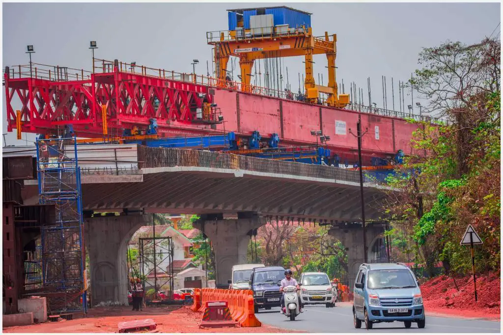
Snow loads and wind actions do not have to be considered at the same time as construction-related loads Qco (i.e. loads due to working personnel). During some temporary design circumstances, however, it may be required to agree on the requirements for snow loads and wind actions to be taken into account simultaneously with other construction loads (e.g., actions due to heavy equipment or cranes) for a specific project.
Thermal and water actions should be evaluated simultaneously with construction loads where possible. When determining optimal combinations with construction loads, the various parameters governing water actions and components of thermal actions should be taken into account where applicable.
In accordance with the relevant parts of EN 1991-2, variable traffic measures should be taken into consideration simultaneously where applicable. Any group of loads, as described in EN 1991-2, shall be taken into account as one variable action for any combination of variable traffic actions with other variable actions stated in other parts of EN 1991.
If the impacts of uneven settlements are regarded as considerable in comparison to the effects of direct interventions, they should be evaluated. Total and differential settlement restrictions may be specified by the specific project. Uncertainty in the assessment of these settlements should be taken into account where the structure is extremely sensitive to uneven settlements.
Uneven settlements on the structure caused by soil subsidence should be defined as a permanent action and included in the structure’s ultimate and serviceability limit state verifications as a combination of actions. Gset should be represented as a set of values relating to differences in settlements between individual foundations or segments of foundations (relative to a reference level), dset,i (i is the number of the individual foundation or part of foundation).
Permanent loads and backfill are the main causes of settlements. For some individual projects, variable actions may need to be considered. Settlements change monotonically (in the same direction) throughout time and must be taken into account from the moment they cause structural impacts (i.e. after the structure or a part of it, becomes statically indeterminate).
Furthermore, there may be a connection between the development of settlements and the creep of concrete members in the case of a concrete structure or a structure with concrete elements. Individual foundation or pair of foundation settlement differences, dset,i, shall be taken into consideration as best-estimate projected values in line with EN 1997, taking into account the structure’s building process.
Groups of Traffic Loads on Highway Bridges
When the simultaneous presence of traffic and non-traffic actions is considerable, the characteristic values of the traffic actions can be calculated using the five separate, mutually exclusive groups of loads listed in Table 4.4a of BS EN 1991-2:2003 (reproduced below), with the dominant component action highlighted. Each load category in the table should be seen as establishing a characteristic action for usage with non-traffic loads, but they can also be used to assess infrequent and frequent values.
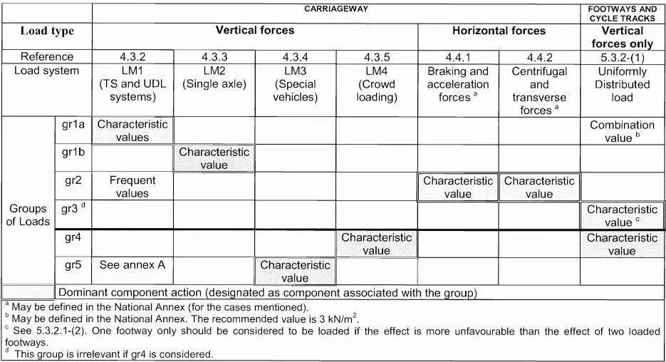
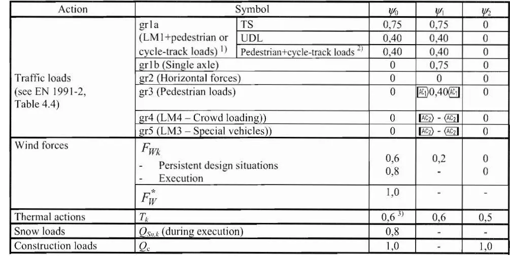
To obtain infrequent combination values it is sufficient to replace in Table 4.4(a) of EN 1991-2 characteristic values with the infrequent ones, leaving unchanged the others, while frequent combination values are obtained by replacing characteristic values with the frequent ones and setting to zero all the others. The ψ-factors for traffic loads on road bridges are reported in the Table below.
Combination Rules for Highway Bridges
(1) The infrequent values of variable actions may be used for certain serviceability limit states of concrete bridges.
(2) Load Model 2 (or associated group of loads gr1b) and the concentrated load Qfwk (see 5.3.2.2 in EN 1991-2) on footways need not be combined with any other variable non-traffic action.
(3) Neither snow loads nor wind actions need be combined with: braking and acceleration forces or the centrifugal forces or the associated group of loads gr2, loads on footways and cycle tracks or with the associated group of loads gr3, crowd loading (Load Model 4) or the associated group of loads gr4. The combination rules for special vehicles (see EN 1991-2, Annex A, Infonnative) with nominal traffic (covered LM1 and LM2) and other variable actions may be referenced as appropriate in the National Annex or agreed for the individual project.
(4) Snow loads need not be combined with Load Models 1 and 2 or with the associated groups of loads gr1a and gr1b unless otherwise specified for particular geographical areas. However, geographical areas where snow loads may have to be combined with groups of loads gr1a and gr1b in combinations of actions may be specified in the National Annex.
(5) No wind action greater than the smaller of Fw* and ψ0Fwk should be combined with Load Model 1 or with the associated group of loads gr1a.
(6) Wind actions and thermal actions need not be taken into account simultaneously unless otherwise specified for local climatic conditions.
Partial Factors for Actions in the Limit State
(1) Design values of actions (EQU) (Set A)

For persistent design situations, the recommended set of values for γ are:
γG,sup = 1.05
γG,inf = 0.95
γQ = 1.35 for road and pedestrian traffic actions, where unfavourable (0 where favourable)
γQ =1.45 for rail traffic actions, where unfavourable (0 where favourable)
γQ = 1.50 for all other variable actions for persistent design situations, where unfavourable (0 where favourable).
γP = recommended values defined in the relevant design Eurocode.
For transient design situations during which there is a risk of loss of static equilibrium, Qk,1 represents the dominant destabilising variable action and Qk.i represents the relevant accompanying destabilising variable actions.
During execution, if the construction process is adequately controlled, the recommended set of values for γ are:
γG,sup = 1.05
γG,inf = 0.95
γQ = 1.35 for construction loads where unfavourable (0 where favourable)
γQ = 1.50 for all other variable actions, where unfavourable (0 where favourable)
(2) Design values of actions (STR/GEO) (Set B)

γG,sup = 1.35 (This value covers the self-weight of structural and non-structural elements, ballast, soil, groundwater and free water, removable loads)
γG,inf = 1.00
γQ = 1.35 for road and pedestrian traffic actions, where unfavourable (0 where favourable)
γQ =1.45 for rail traffic actions, where unfavourable (0 where favourable)
γQ = 1.50 for all other variable actions for persistent design situations, where unfavourable (0 where favourable). This value covers variable horizontal earth pressure from groundwater, free water, and ballast, traffic load surcharge earth pressure, traffic aerodynamic actions, wind, and thermal actions, etc.
γP = recommended values defined in the relevant design Eurocode.
γGset (partial factor for settlement) = 1.20 in the case of linear elastic analysis, and γGset = 1.35 in the case of non-linear analysis, for design situations where actions due to uneven settlements may have unfavourable effects.
ξ = 0.85 (so that ξγG,sup = 0.85 x 1.35 = 1.15)
(3) Design values of actions (STR/GEO) (Set C)

γG,sup = 1.00
γG,inf = 1.00
γGset = 1.00
γQ = 1.15 for road and pedestrian traffic actions where unfavourable (0 where favourable)
γQ = 1.25 for rail traffic actions where unfavourable (0 where favourable)
γQ = 1.30 for the variable part of horizontal earth pressure from soil, groundwater, free water and ballast, for traffic load surcharge horizontal earth pressure, where unfavourable (0 where favourable)
YQ = 1.30 for all other variable actions where unfavourable (0 where favourable)
γGset = 1.00 in the case of linear elastic or non linear analysis, for design situations where actions due to uneven settlements may have unfavourable effects. For design situations where actions due to uneven settlements may have favourable effects, these actions are not to be taken into account.

