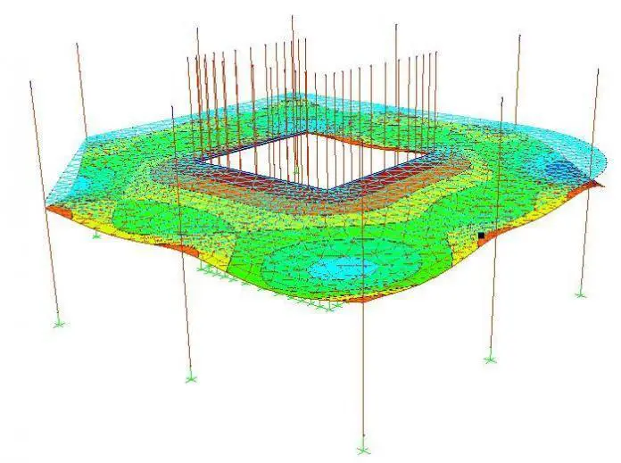
Deflection is the movement of a point on a structure or structural element, usually measured as a linear displacement or succession displacements transverse to a reference line or axis. Thus, deflection can be said to be a deformation that occurs over time on a structure or structural element under a load. The primary material parameters influencing concrete deflection are temperature, modulus of elasticity, shrinkage, modulus of rupture, and creep.
Deflection is a vital serviceability limit state criterion in the design of reinforced concrete structures. Therefore, structural designers must always consider deflection and ensure compliance with acceptance criteria for deflection as stated in RC design codes such as BS 8110, EC 2 and IS 456.
This article will discuss the theory of deflection of slabs and thin plates, the effects of deflection on the performance and functionality of RC buildings, factors affecting the deflection of RC slabs, methods of assessing the deflection of slabs, how to control deflection during design, and how to remedy a building failing in deflection.

Beam theory of slab deflection
Slabs are common structural elements of RC building structures, taking up nearly 50% of the total weight of buildings. Slabs are usually analyzed under transverse loading, and the slab thickness governs the serviceability requirement for deflection. Therefore, structural designers need to properly analyze slabs to choose the minimum slab thickness satisfying the deflection criterion and minimizing the building’s weight.
The deflection theory of slabs is similar to that of beams. However, it is more complex. Consequently, we will adopt a simplified approach for one-way and two-way spanning slabs.
One-way slabs

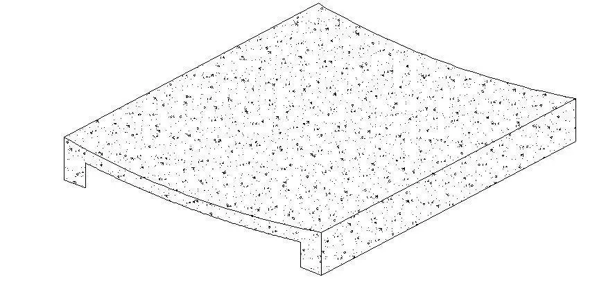
Given the figures above, the slabs are analyzed as a beam with the bending moments per unit strip. As shown in (a), one-way slabs are supported on two opposite sides. The load transfer and structural action are usually in one direction along the slab’s shorter span (la) or perpendicular to the supporting beams. Thus, we can say that the slab consists of a single parallel strip.

To derive the deflection equation, we assume the strip acts like a simply supported beam uniformly loaded across its length (l). Thus, the general slope and deflection equations can be derived using the double integration method, as shown below.
General slope equation: dy(EI/dx) = wlx2/4 – wx3/6 – wl3/24
General deflection equation: yEI = wlx3/12 – wx4/24 – wl3x/24
Since maximum deflection occurs at the mid-span of the strip, that is, where x = l/2
Then, substituting x = l/2 into the deflection equation gives the resulting equation below.
Maximum deflection at mid-span: y = 5wl4/384EI
Two-way slabs
Similarly, the two-way slab in (b) is essentially supported on all four sides, and the load transfer and structural action are in two directions resulting in biaxial bending moments. Thus, we can say that the slab consists of a parallel strip in each direction (la and lb), and they intersect each other. Consequently, the load supported by the slab is shared between the two strips though dominant in the direction of the shorter span (la).
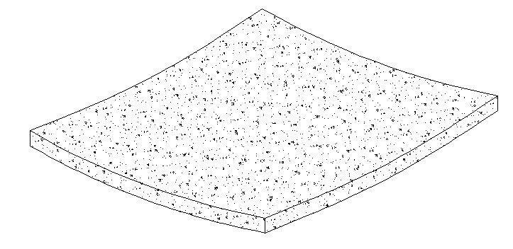
Furthermore, it is proper to assume that the mid-span deflections in the two-way slab at the point of intersection are equal since the strips are part of the same slab. Therefore, under a uniformly distributed load (w) per square metre, each strip takes its share of w as wa and wb, and the deflection equations are given below.
5wala4/384EI in the shorter direction
5wblb4/384EI in the longer direction
It must be noted that the maximum deflection equations above hold for simply supported end conditions. Thus, the maximum mid-span deflection is wl4/192EI for hinged-fixed end conditions and wl4/384EI for fixed-fixed end conditions.
Deflection of thin plates
Plates are defined as plane structural elements with a small thickness compared to other dimensions of the plate. As a result, plates resist applied loads employing bending in two directions and twisting moment. Thus, the plate theory takes advantage of the disparity in length scale to reduce the entire 3-D solid mechanics problem to a 2-D problem.
Furthermore, plates are categorized into thick, thin, and membranes depending on thickness to width ratio. For example, if a plate’s thickness to width ratio is less than 0.1 and the maximum deflection is less than one-tenth of the thickness, then the plate is classified as a thin plate structure.
Several plate theories are associated with geometric assumptions, such as the Kirchhoff plate theory, the Reissner-Mindlin plate theory, the von Karman plate theory, and the Timoshenko plate theory. Below, the Timoshenko plate theory is briefly discussed.
One-way slabs
Timoshenko’s plate theory for cylindrical bending of uniformly loaded rectangular plates with simply supported edges can be used for one-way slabs because the bending nature of such slabs can be simulated as thin plates with small deflections. Thus, the governing differential equation for the deflection curve is given below:
–M = D(d2w/dx2) and,
D = Eh3/12(1-v2)
Where D is the Flexural rigidity of the plate, E is the modulus of elasticity of the plate material, v is the Poison’s ratio, h is the thickness of the plate, and the variable quantity ‘w’ is the transverse deflection of the middle plane of the plate.
Thus, the maximum deflection for simply supported conditions is at the center, and it is given by: w = 5ql4/348D
Where q is the UDL loading intensity on the plate and l is the length of the plate along supported edges.
Two-way slabs
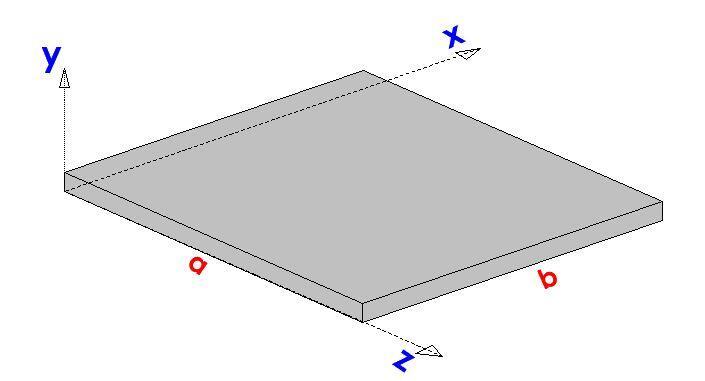
For a two-way, rectangular plate with sides a and b, as shown above, the derivation of the maximum deflection at the center of the plate involves rigorous analysis. Thus, it would not be considered in this article. However, if we assume that the plate is instead square such that sides a and b are equal, then the maximum central deflection is given below.
w(max) = 4qa4/π6D = 0.00416qa4/D
Effects of deflection on building performance and functionality
It is true that buildings move and experience vibrations. However, designing a building aims to achieve a state of static equilibrium. The state of equilibrium is to be among the parts of the constructed building and the forces acting on it. Therefore, deflection is one of the movements in buildings affecting performance and functionality.
Excessive deflection of flexural members above those the structural designer allows can result in several difficulties for building occupants. These difficulties include cracking of wall, floor and ceiling finishes, unsightly and unacceptable appearance or visual effects, impaired functionality, alarm and discomfort to building occupants, and damaged roof membranes and supported partitions.
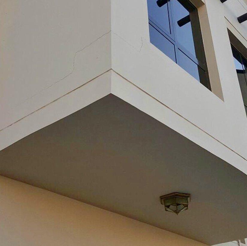
Additional potential problems associated with slab deflection include jamming doors and windows, gaps between partitions and floors and between columns and floors, and visual perception of sagging floors and ceilings. Furthermore, deflection can worsen over time and lead to additional maintenance costs and structural problems.
Moreover, a suspended floor slab must be serviceable during the life of a building. Therefore, it is expected that the top profile of a slab does not show any sign of deflection. However, occupants of a building can decide to change the use of a building or space if they perceive any deflection on a floor slab surface under sustained loading. For example, an occupant can convert a building or space from an office, institutional, educational or industrial use to general domestic use.
Factors affecting the deflection of RC slabs
Several factors affect the deflection of RC slabs, and a holistic and accurate assessment of slab deflections can only be achieved if consideration is given to these factors. Furthermore, the factors affecting slab deflections vary intrinsically and may change with time. For example, factors such as elastic modulus, creep coefficient, and tensile strength of concrete significantly influence the final slab deflections.
Furthermore, some factors are influenced by others. Consequently, deflection calculations remain an estimate because of the variability of several factors. Therefore, the technical report (TR58) of a joint project of the British Cement Association, The Concrete Centre, and The Concrete Society advises that actual deflection may vary from calculated deflections in a range of -30% to +15%. The report also discusses the rigorous method of estimating slab deflections and the factors influencing deflection.
Some of the factors affecting slab deflections are discussed below.
Boundary Conditions
The boundary conditions of a slab have a profound effect on the deflection behaviour of the slab. Fully fixed supports will have less deflection compared to simple supports. Monolithic and/or continuous supports also have a more positive effect on deflection compared to corners that are free to lift.
Concrete Tensile Strength
Generally, slab designs are closer to the cracking load, and small property or loading variation can cause a slab to crack and thus deflect more. Therefore, the tensile strength of concrete is an essential property because a slab will crack once the tensile stress in the extreme fibre is exceeded. To reduce slab deflection, then tensile strength must be increased. This can be achieved by increasing concrete compressive strength because tensile strength is proportional to the square root of compressive strength.
Aggregate properties
Fine and coarse aggregates comprise about 70% of a typical volume of concrete. Thus, aggregates significantly influence the elastic modulus of concrete. Therefore, slab deflection will increase substantially if poor-quality aggregates are used.
Relative humidity (RH)
According to TR58, it is reported that predicted deflection will decrease with increasing RH. For example, an RC slab in an outdoor environment with RH between 80 – 85% is likely to have deflections about 20% lower than another slab in an indoor environment with RH between 45 – 50%.
Ambient Temperature
The hydration of cement is usually slower at a lower temperature. Therefore, a concrete slab cast under low ambient temperature will experience low strength gain and, consequently, more likely to deflect even under its self-weight.
Time of loading
The effect of early-age loading or overloading of slabs has pronounced effects on deflection, especially when the age of the slab is less than 5 days. However, the further difference in deflection is minimal.
BS 8110 methods of assessing slab deflections
Two methods can check the deflection of slabs according to BS 8110. It is important to know that in the design of RC slabs, deflections are checked in the shorter span, which is more critically loaded. The two methods of checking the deflection of slabs are discussed below.
The first method is guided by the maximum limits of deflections based on slab spans given by the code. For example, BS 8110-2:1985 states that the sag in a concrete member will become visible once deflection exceeds span/250. Therefore, if a structural designer knows the maximum slab deflection for the relevant load case, he can check whether it is within the limit given in Section 3 of BS 8120-2:1985.
Conversely, the second method limits the basic span–effective depth ratio to specific values given in Table 3.9 of BS 8110-1:1997 depending on the slab boundary condition type.
| Support Condition | Rectangular Section | Flanged beam with bw/b ≤ 0.3 |
| Cantilever | 7 | 5.6 |
| Simply supported | 20 | 16.0 |
| Continuous | 26 | 20.8 |
Furthermore, structural designers should modify the values given in Table 3.9 by multiplying them with the factors for tension and compression reinforcements given in Tables 3.10 and 3.11, respectively.
Modification factor = 0.55 + (477 – fs)/[120(0.9 + M/bd2)] ≤ 2.0
Where M is the ultimate moment at the centre of the span or at the support of a cantilever.
fs = service stress = 2fyAsreq/3Asprov
Modification factor for compression reinforcement = 1 + (100A’sprov/bd)/(3 + 100A’sprov/bd) ≤ 2.0
Eurocode 2 (EN 1992-1-1) Methods of Assessing Deflection
In Eurocode 2, the deflection of a structure may be assessed using the span-to-effective depth ratio approach, which is the widely used method. It is also allowed to carry out rigorous calculations in order to determine the deflection of a reinforced concrete structure, which is then compared with a limiting value.
According to clause 7.4.1(4) of EN 1992-1-1:2004, the appearance of a structure (beam, slab, or cantilever) may be impaired when the calculated sag exceeds span/250 under quasi-permanent loads. However, span/500 is considered an appropriate limit for good performance.
Using the span-to-effective depth approach, the deflection of a structure must satisfy the requirement below;
Allowable l/d = N × K × F1 × F2 × F3 ≥ Actual l/d
Where;
N is the basic span-to-effective depth ratio which depends on the reinforcement ratio, characteristic strength of the concrete, and the type of structural system. The expressions for calculating the limiting value of l/d are found in exp(7.16) of EN 1992-1-1:2004. The expressions are given as follows;
l/d = K[11 + 1.5√fck(ρ0/ρ) + 3.2√fck(ρ0/ρ – 1)1.5] if ρ ≤ ρ0
l/d = K[11 + 1.5√fck(ρ0/(ρ – ρ’)) + 0.0833√fck(ρ0/ρ)0.5] if ρ > ρ0
Where:
l/d is the limit span/depth ratio
K is the factor to take into account the different structural systems
ρ0 is the reference reinforcement ratio = √fck /1000
ρ is the required tension reinforcement ratio at midspan to resist the moment due to the design loads (at supports for cantilevers)
ρ’ is the required compression reinforcement ratio at midspan to resist the moment due to the design loads (at supports for cantilevers)
fck is the characteristic compressive strength of the concrete in N/mm2
The values of K for different structural systems are given in the Table below;
| Structural System | K |
| Simply supported beam, one or two way spanning simply supported slab | 1.0 |
| End span of continuous beam or one-way continuous slab or two-way spanning slab continuous over one long side | 1.3 |
| Interior span of beam or one way or two-way spanning slab | 1.5 |
| Slab supported on columns without beams (flat slab) | 1.2 |
| Cantilever | 0.4 |
F1 = factor to account for flanged sections (not applicable to slabs) = 1.0
F2 = factor to account for brittle partition in long spans.
In flat slab where the longer span is greater than 8.5m, F2 = 8.5/leff
In beams and slabs with span in excess of 7.0m, F2 = 7.0/leff
F3 = factor to account for service stress in tensile reinforcement = 310/σs ≤ 1.5
Conservatively, if a service stress of 310 MPa is assumed for the designed reinforcement As,req, then F3 = As,prov/As,req ≤ 1.5
More accurately, the serviceability stress in the reinforcement may be estimated as follows;
σs = σsu[As,req/As,prov]((1/δ)
Where;
σsu is the unmodified SLS steel stress taking account γM for reinforcement and of going from ultimate actions to serviceability actions.
σsu = fyk/γs(Gk + ψ2Qk)/(1.25Gk + 1.5Qk)
As,req/As,prov = Area of steel required divided by the area of steel provided.
How to control slab deflection during design
Deflection control is a vital serviceability requirement in the design of RC building structures because slabs will crack due to excessive deflections if deflection control is not adequately considered. Although providing an adequate safety level against collapse is the primary design consideration, structural designers must consider the possible adverse effects of excessive deflections on the performance and functionality of a structure at service load levels.
Furthermore, design codes guide how to control slab deflection, which will be perfectly adequate and provide economical solutions for most building designs. However, such methods are semi-empirical, and while approximate deflection estimates may be made, they are not intended to predict how much a member will deflect over time.
Deflection in reinforced concrete slabs can be reduced or controlled by increasing the thickness of slab, increasing the area of steel provided, modifying the structural scheme by reducing the span, or reducing the dead load on the slab. Sometimes, two or more of these solutions are required in order to keep the deflection of slab to a minimum.
Increase slab depth
Stiffness plays an essential role in the design of RC slabs because it indicates the ability of the slab to return to its original shape or form after an applied load is removed. Thus, stiffness directly influences slab deflection. Consequently, if stiffness increases, the less the slab deflects under a load because stiffness is inversely related to deflection.
For example, stiffness is EI/L, and the moment of inertia (I) is bh3/12 for a regular, uncracked rectangular section. Therefore, increasing the dimension b or h of a slab would result in a reduced value for the deflection. However, it must be noted that the effect of increasing depth (h) is much more dominant than that of increasing width (b), especially in slabs.
Increase the area of steel provided
By increasing the area of steel, the service stress in the reinforcement reduces, and increases the modification factor for deflection control. However, there is a limit to which increment of area of steel can go.
Reduce slab span
Reducing a slab’s shorter span helps reduce deflection since deflection is also a function of the basic span–effective depth ratio (lx/d). Thus, if lx is reduced, then deflection reduces, and vice-versa. However, it is essential to note that reducing slab spans may not be possible in all cases as it involves introducing new columns and beams and depends on floor layout and architectural requirements for spaces.
Reduce additional dead loads
Additional dead loads on slabs include loads from partition walls and floor finishes. Therefore, alternative, lightweight materials for partition walls and floor finishes will help reduce long-term dead load application on slabs.
Remediation of deflected slabs
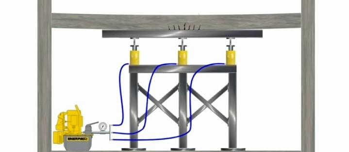
Since deflection control is a serviceability consideration, thus, small slab deflections may necessarily not lead to collapse. However, large deflections may lead to slab collapse if necessary actions are not taken to remedy the slab. Let’s look at the overlay method of fixing an existing deflected slab.
The overlay method seems to be the most practical way of remedying a slab after deflection. It involves increasing the stiffness of the slab while reducing deflection. However, the process must be carried out by experts. The steps of the overlay method are listed below.
1. Design and install lifting system.
2. Start lifting of slab from the soffit according to the recommended force.
3. Inject the cracks formed at the top of the slab due to adverse lifting force.
4. Lightly chip the surfaces of the slab and supporting columns.
5. Drill holes in the slab and supporting columns to receive new dowels.
6. Clean the drilled holes with pressurized air.
7. Fill the holes with epoxy materials to aid bonding between steel dowel bars and anchors with the concrete.
8. Insert anchors and main steel in the drilled holes.
9. Apply bonding materials on the anchor and main steel bars.
10. Cast the new concrete material on the existing slab.
11. Allow curing for at least 14 days.
12. Remove lifting system.
Perhaps you are interested in a visual aid for the overlay method; then you can click this link.
Worked Example on Deflection of Slab (BS 8110)
Conduct the deflection check for a continuous slab with the data given below.
Effective depth (d) = 124 mm
Area of steel required = 681.48 mm2 per m run
Area of steel provided = 754 mm2 per m run
Slab span = 3900 mm
Steel strength (fy) = 380 N/mm2
Allowable span/depth ratio = 26
Bending moment (M) = 27.15 kNm
Solution
Service stress (fs) = (2fyAs req)/(3As prov) × (1/δb), Where δb = 1
fs = (2 x 380 x 681.48) / (3 x 754) x (1/1) = 229 N/mm2
Bending stress = M/bd2 = (27.15 × 10⁶) / (1000 × 1242) = 1.766 N/mm2
Modification factor = 0.55 + [(477 – service stress) / (120(0.9 + bending stress))] ≤ 2
M.F = 0.55 + [(477 – 229) / (120(0.9 + 1.766))] ≤ 2
M.F = 1.28 < 2 (ok)
Allowable span-depth ratio = 26 × 1.28 = 33.28
Actual span-depth ratio = 3900 / 124 = 31.45
Since allowable span-depth ratio is greater than actual span-depth ratio (33.28 > 31.45), deflection is ok!
Worked Example on Deflection of Slab (EN 1992-1-1)
Let us design and evaluate the deflection of a two-way slab according to Eurocode 2.
Lx = 3.625 m
Ly = 3.825 m
fck = 25 MPa
fyk = 460 MPa
Total dead load (gk) = 6.45 kN/m2
Leading variable action (Imposed load) qk1 = 1.5 kN/m2
Total load on slab (ULS) = 1.35gk + 1.5qk = 1.35(6.45) + 1.5(1.5) = 10.9575 kN/m2
Design of the short span
Mid span
MEd = αnlx2 = 0.042 × 10.9575 × 3.6252 = 6.0475 kNm/m
As1 = MEd/(0.87fykz) = (6.0475 × 10⁶)/(0.87 × 460 × 0.95 × 119) = 133.668 mm2/m
Provide Y12mm @ 250mm c/c BOT (ASprov = 452 mm2/m)
Minimum Area of Steel Required
fctm = 2.5649 N/mm2 (Table 3.1 EC2)
As,min = 0.26 × fctm/fyk × b × d = 0.26 × 2.5649/460 × 1000 × 144 = 208.76 mm2/m
Check if As,min < 0.0013 × b × d (187.2 mm2/m)
Since, As,min = 187.2 mm2, the provided reinforcement is adequate.
Check for deflection
We check for deflection at the short span of slabs
k = 1.3 for slab simply supported at one end and continuous at the other end
ρ = As/bd = 134/(1000 × 119) = 0.001126 < 10-3√fck (0.005)
Since ρ < ρ0
L/d = K [11 + 1.5√(fck) ρ0/ρ + 3.2√(fck) (ρ0/ρ – 1)3⁄2]
L/d = 1.3 [11 + 1.5√(25) × 0.005/0.001126 + 3.2√25 (0.005/0.001126 – 1)3⁄2] = 1.3(44.3 + 102.106) = 190.327
Modification factor βs = 310/σs
σs = (310fykAs,req)/(500As,prov) = (310 × 460 × 133.688)/(500 × 452) = 84.341 N/mm2
βs = 310/84.342 = 3.67 > 2.0 (take 2.0)
Taking the distance between supports as the effective span, L = 3625 mm
The allowable span/depth ratio = βs × 30.838 = 2.0 × 190.327 = 280.645
Actual deflection L/d = 3625/119 = 30.462
Since 280.645< 30.462 Therefore, deflection is ok.
Conclusion
Structural designers and building contractors continue to employ reinforced concrete for suspended floor slabs in building structures because of its durability and economic benefits. However, short and long-term deflection remains a concern. Therefore, structural engineers and other professionals in the building construction industry must understand the implications of slab deflection and make adequate design allowances to accommodate it.
References
[1] TR58 (2005), Technical Report No. 58: Deflections in Concrete Slabs and Beams, The Concrete Society, Camberley, UK.
[2] BS 8110 (1997), Structural Use of Concrete – Part 1: Code of Practice for Design and Construction, British Standards Institution, London.
[3] BS 8110 (1985), Structural Use of Concrete – Part 2: Code of Practice for Special Circumstances, British Standards Institution, London.
[4] Priyanka, M. D. and Ramesh, V (2022), Comparative Study on Slab Deflections, IOP Conference Series: Earth and Environmental Science, Vol. 982, available at: https://iopscience.iop.org/article/10.1088/1755-1315/982/1/012081
[5] RC Design II: One-way and Two-way slabs, University of Asia Pacific, Dhaka, Bangladesh, available at: https://www.uap-bd.edu/ce/anam/Anam_files/RC%20Design%20II.pdf

