Steel cables are frequently used within form-based structures in the family of designs known as lightweight tension structures. For a variety of reasons, the solutions are appealing for unique constructions like roofs and bridges. Cables have a high strength capacity that is around three times that of standard steel, and because of their low weight per unit of strength, less steel is needed to support weights.
Reduced structural sections and self-weight can result in considerable gains in overall structural efficiencies and costs because self-weight loading can make up the majority of the loading that needs to be resisted in large bridges and roofs. Due to their narrow cross-section, cables are appealing in applications that aim to optimise transparency, such as supporting glass facades, and reduce shadowing, such as supporting roofs.
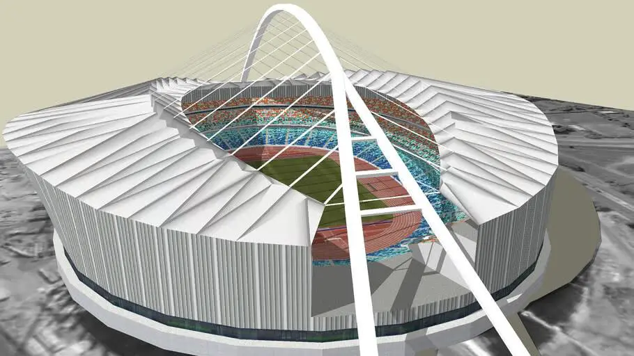
The low bending stiffness of cables is not a limitation, but rather a unique property that gives engineers several design options. In order to ensure that cables withstand forces effectively under axial stress, many lightweight cable systems are purposefully form-found. However, cables can be designed to handle lateral load, ‘compression’, and tension forces.
In Eurocode 3 (Part 11), cables are categorised under group B of tension components. They usually comprise of wires which are anchored in sockets or other end terminations and are fabricated primarily in the diameter range of 5mm to 160 mm.
Spiral strand ropes are spiral rope comprising only round wires. They are normally used for stay cables for aerials, smoke stacks, masts and bridges. They are also used as hangers or suspenders for suspension bridges, stabilizing cables for cable nets and wood and steel trusses, and hand-rail cables for banisters, balconies, bridge rails and guardrails.
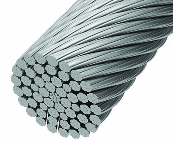
Fully locked coiled rope is a spiral rope having an outer layer of fully locked Z-shaped wires. They are fabricated in the diameter range of 20 mm to 180 mm and are mainly used as stay cables, suspension cables and hangers for bridge construction, suspension cables and stabilizing cables in cable trusses, edge cables for cable nets, and stay cables for pylons, masts, and aerials.
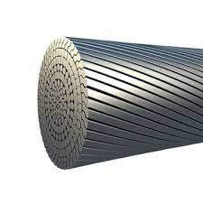
Structural strand ropes are mainly used as stay cables for masts, aerials, hangers for suspension bridges, damper / spacer tie cables between stay cables, edge cables for fabric membranes, rail cables for banister, balcony, bridge, and guide rails.
Load Resistance of Cables
The ways in which cables resist load could be by tension, compression, or lateral load resistance.
(1) Tension Load
Guy cables conveying axial load from end to end are the most frequent occurrence of axial tension in cables. The performance is characterised by elastic stiffness, and the behaviour is roughly comparable to that of any tension element, be it a beam or a rod. However, “tension stiffness” becomes important if the tensile stress is significant.
(2) Compression Load
Cables can only resist compression if prestressed by self-weight or an internal self stress. However, the net axial load must be tension.
(3) Lateral Load
The initial elastic stiffness and lateral load resistance of cables are quite low. Instead of bending to resist the load, they will shift to an equilibrium position where they can resist it by applying axial stress to the cable. The shape changes to a catenary for a cable that is uniformly loaded. Although this is a well-known form, it rarely appears in such a pure sense in actual practise. Since cables are frequently loaded at specific locations along their length, the equilibrium form develops facets.
Linear, Non-Linear and Large Displacement Behaviour of Cable Structures
The level of analysis and evaluation necessary for cable structures can be very imprecise. The following sources of non-linearity in cable systems:
- Individual cable elements loaded axially or laterally experience tension stiffening.
- displacements of the entire system, which are typically regarded as “large” displacements, such as cables becoming slack and leaving the main structural system.
- a cable system’s overall state of equilibrium against forces
In terms of behaviour, cable-stayed structures are similar to linear elastic structures. The consequences of non-linearity can be minimal in structural systems using “straight cables” based on applied tension and compression stresses to the cable ends, allowing for extensive initial study on straightforward linear programmes. The effects of a structure’s non-linearity will typically be minimal if it is “noded out” and may be solved by hand or computer.
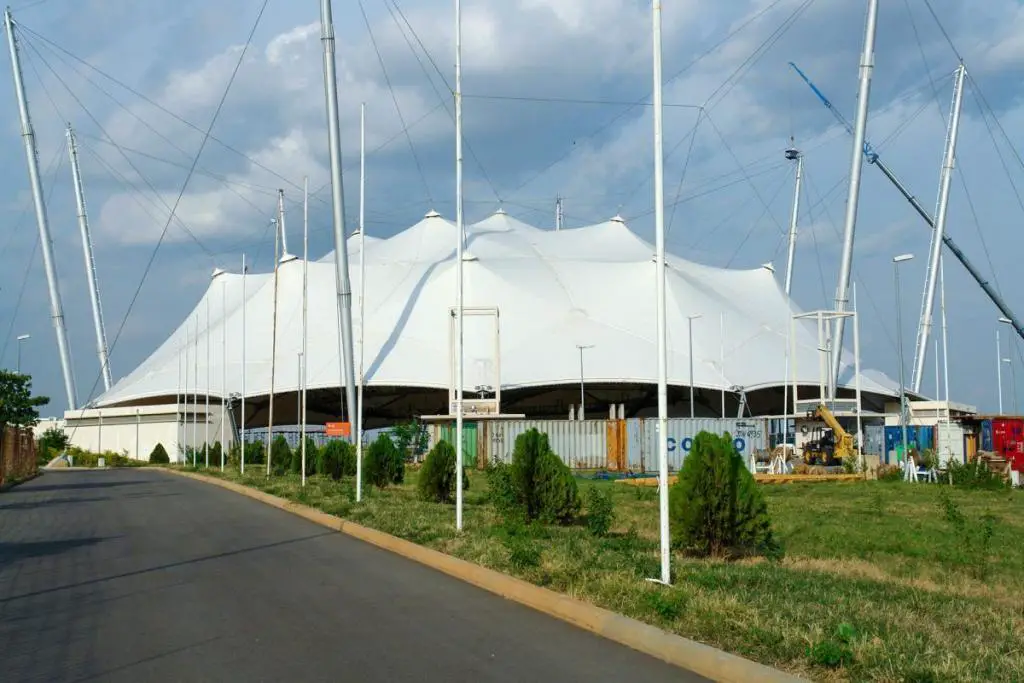
Cable structural systems laterally loaded experience minimal initial elastic resistance as they assume their equilibrium shape. These require to be analysed under loads using software that can handle the geometrically non-linear behaviour and are typically referred to as cable net constructions. In this situation, the structure can’t be classified as “noded out” or statically determined, like a Warren truss, for example.
In this case, non-linear programming are necessary even though simple manual computations can help suggest a solution. These typically solve the structural equations incrementally step-by-step to advance the structure from an initial beginning state to a final equilibrium point. Dynamic relaxation is a well-known method.
To arrive at an equilibrium figure, the initial geometry of cable net structures must be form-found. The prestress forces can be introduced into a nonlinear programme as previously described using constant force elements. This procedure involves adjusting the cable stiffnesses and specified forces until the required form is obtained.
The cable lengths and tensions are determined from this geometry, which produces the final geometry. The cables must be cut to the calculated lengths for the structure, taking into account both elastic stretch and inelastic, or “building” stretch. Engineers with experience are required to carry out this operation due to its complexity.
Structural Solutions using Cables
Tension structures categorise into a number of groups, each of whose form is tied to the function of the cables—that is, how the cable is loaded and how it resists loads. Several of these functions may be included in a complex structure, but the primary groups are depicted below;
Cable Stayed Structures
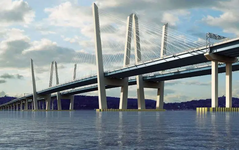
The Tappan Zee Cable Stayed Bridge
The typical characteristics of cable stayed structures are that the cables are loaded axially from one end to the other, and the cable end nodes typically support steel beams or trusses. A typical application is for cable stayed bridges, e.g. Queen Elizabeth II Bridge. Some other applications for roofs are numerous and include the Inmos, Newport and National Dartford, and the Second Severn Crossing Exhibition Centre, Birmingham..
Suspension Structures
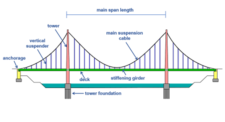
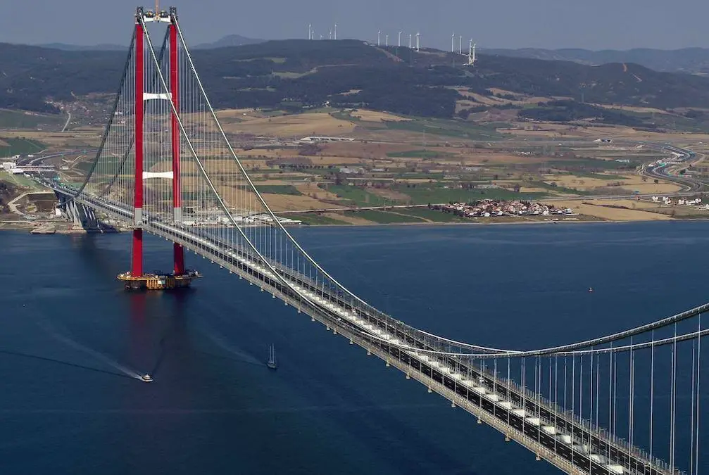
The cables in suspension structures are loaded laterally. Suspension bridges, like the Old Severn Crossing, are the most common application, and in these constructions, a catenary or parabolic cable serves as the main support for the hangers and deck. The primary cable is stressed by the dead load of major suspension structures, where the dip to span ratio is typically more than 1:12. In this instance, the deflection is not much affected by the stretch of the cable.
Surface Stressed Structures
In structures using surface-stressed cable, the cables are first prestressed against the supporting members to create a state of self-stress before being loaded laterally. Nonlinear computations must be utilised to determine the deflections and forces because the cable extension is important for the deflections. Individual straight cables or a network of cables that are essentially at right angles to one another can make up the structure.
Depending on the 3D form, a cable net may be flat or prestressed. Calculations using displacements to the equilibrium position are the only way to determine the initial geometry since it is determined by the equilibrium of the tension forces under the first prestress forces. The final geometry is similarly only determined by calculations involving displacements to the equilibrium position and is determined by the equilibrium of the tension forces under the forces arising from the pre-stress and applied loading.
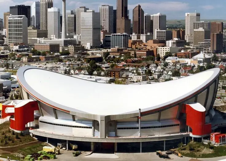
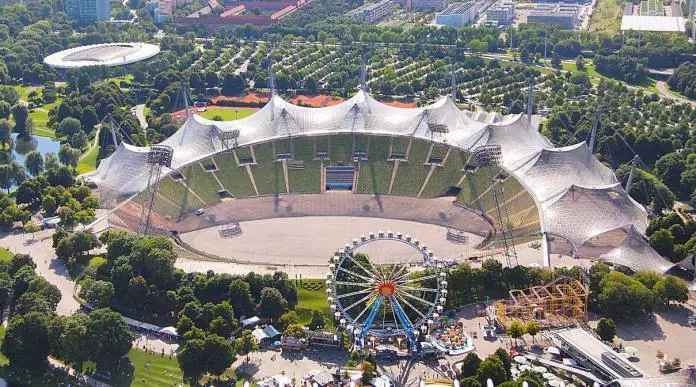
In numerous recent applications, facades are held against lateral wind loading by cables in a single flat plane. Typically, deflections are large, and cable nets have been successfully used to create aviary enclosures at Munich Zoo, as well as other notable examples like Calgary Olympic Saddledome and Munich Olympic Stadium, built in 1972.
2D Cable Trusses
Fully triangulating a cable truss allows the individual components to resist loads by applied tensions at the end nodes. However, the phrase “cable truss” is frequently (and possibly mistakenly) used to characterise systems where the cable resists load laterally and the system is not entirely triangulated (see figure below). They are an example of a surface-stressed structure specifically chosen for its funicular geometry to the most typical loading. This method has frequently been utilised to hold back vertical facades against wind loading.

3D Cable Net
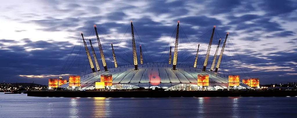
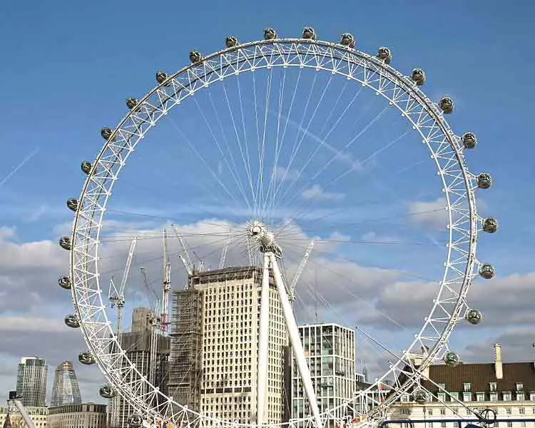
The term “3D cable net” is used as a general name for some of those structures that may have cables working in diverse ways, although it does not fully characterise the nature of some sophisticated unique systems. Using straight cables that are all “noded-out,” certain constructions have been built in three dimensions that withstand loads by direct axial tension. The BA London Eye is one example of such application. The Millennium Dome, Greenwich is another example that use cables loaded laterally.
Analysis and Design Issues for Cable Structures
The following are analysis and design issues associated with cables and cable structures;
Codes of Practice:
In Europe, Eurocode 3 (EC3), Part 1-11, BS EN 1993-1-11, Design of structures with tension components, is the most pertinent design standard for cable structures. There are other industry manuals created for post-tensioned concrete and bridges contain information about cables.
Types of Steel Cables
According to Eurocode 3, types of steel cable includes spiral strand rope, strand rope, locked coil rope, and parallel wire strand.
Cable Stiffness:
Both the material modulus and the length changes brought on by winding the strands and ropes play a role in the stiffness of cables. Testing or manufacturing data must be used to get precise values. In contrast to strength, cables are typically sized for stiffness.
Working stress or load factor design:
Early cable design pioneers for buildings used a working stress design. Because some engineers believe that form-found structures are more suited to working stress design, cable structures have seen a slow transition to load factor design. The brand-new Eurocodes use a load factor approach.
Cable strength:
Manufacturers typically refer to cable strength as the Minimum Breaking Load (MBL). In the past, working load approaches with low utilisation factors in comparison to breaking strengths were used to design cables. In most cases, the maximum unfactored force is restricted to 50% MBL.
To make sure that various manufacturers are employing the same strategy for fatigue within their reported MBL, attention must be taken when converting the MBL to design values using either working stress or limit state approaches. The ultimate limit state approach is becoming more popular. Additionally, it is important to make sure that the connector designs are more robust than cables.
In EC3, an empirical factor used in the determination of minimum breaking force of a rope is obtained as follows:
K = πfk/4
where f is the fill factor for the rope and k is the spinning loss factor.
The minimum breaking force Fmin is given by;
Fmin = d2RrK/1000
where d is the diameter of the rope in mm, K is the breaking force factor, Rr is the rope grade in N/mm2
Load factors:
The general non-linearity of lightweight tension structures necessitates the use of load factors with particular caution to produce a set of loading circumstances that is safe, effective, and realistic. In comparison to other structures, the behaviour of this structure in response to changes in components must be understood from first principles and at a higher level of understanding. For different steel parts in the same structure, such as steel cables and steel tubes, it may occasionally be necessary to use both a working load approach and an ultimate limit state approach.
Generally, load factors will be the same as for other buildings. Prestress should be taken into consideration with caution. Dead loading and its contributing components are sometimes grouped with prestress loading. However, the load components should be viewed as independent variables if these are not related (for instance, if the prestress is jacked into the system).
Maximum force in the lower cables and minimal force in the upper cables were crucial design considerations for the BA London Eye (to ensure they remained active and did not go slack). The load factors for prestress, which were distinct from the load factors for dead load as indicated below for two generic loadcases, were used to calculate the extreme values of forces in the cables:
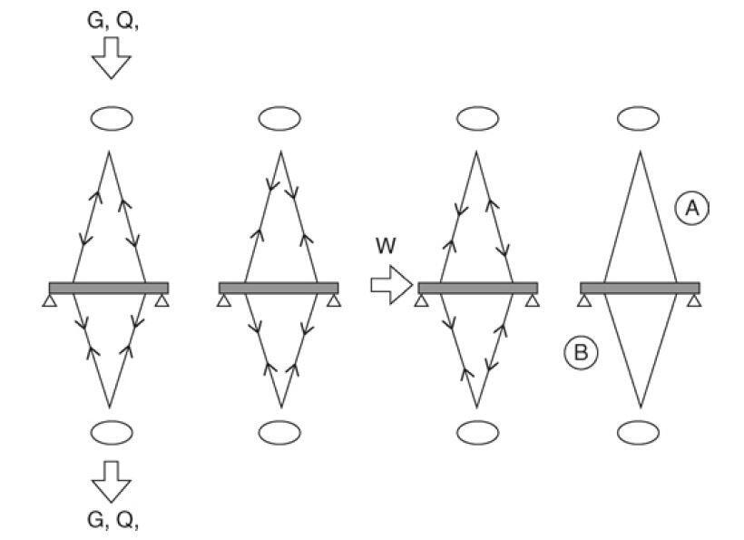
For derivation of the maximum tension in the lower cables ‘B’:
γfmax G + γfmax Q + γfmax PS + γfmax W
For derivation of the minimum tension in the upper cables ‘A’:
γfmax G + γfmax Q + γfmin PS + γfmax W
Construction stretch and cable compensation:
It’s important to understand how design tolerances for cable length affect the final product. Pre-stretched cables should be used, and turnbuckles or other adjustable length connectors can be fitted.
Cable vibration:
It’s important to examine cables for the impacts of wind-induced vibration, such as vortex shedding or galloping, and rain-induced vibration.
Fatigue Loading:
Even if aeroelastic instabilities are not at their worst, cables still need to be examined for fatigue loading.
Cable end connectors:
Movements during installation and maintenance cause connections to spin and move substantially more than typical steelwork connections. Fork end connections are typical for cable systems and permit rotation about one axis; however, unique connections can be needed to accommodate larger-than-normal rotations along several axes.
Cable saddles and diverters:
Because cable end connections are expensive, it is preferred to pass a large-diameter cable through a joint using a saddle, clamp, or diverter, if it is practical to do so. These joints require evaluation of concerns such as axial cable stress reduction, friction capacity, acceptable bearing stress, and installation-related Poisson’s ratio impacts.





Is the book available