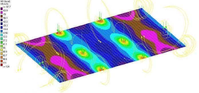
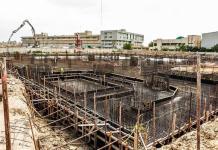
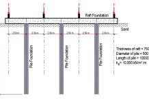
When settlements of foundation could be an issue, such as when a site has erratic deposits or lenses of compressible materials, suspended boulders, etc., mat foundations are frequently used. Settlement of mat foundations has been observed to be lower compared to spread footing.
It is impossible to completely eliminate the settlement of shallow foundations founded on natural soils. At least, the immediate (elastic) must occur, before the consolidation settlement will begin, if the foundation is founded on clay. The following methods are frequently used to control the settlement of foundations during the design of foundations:
- Making use of a larger foundation to reduce soil contact stresses
- Displaced volume of soil (flotation effect); in theory, the system “floats” in the soil mass and no settlement takes place if the weight of the excavation is equal to the total weight of the structure and mat (see design of bouyancy raft foundation).
- Bridging effects attributable to mat rigidity and contribution of superstructure rigidity to the mat.
- Allowing bigger settlements that are 50 mm instead of 25 mm larger.
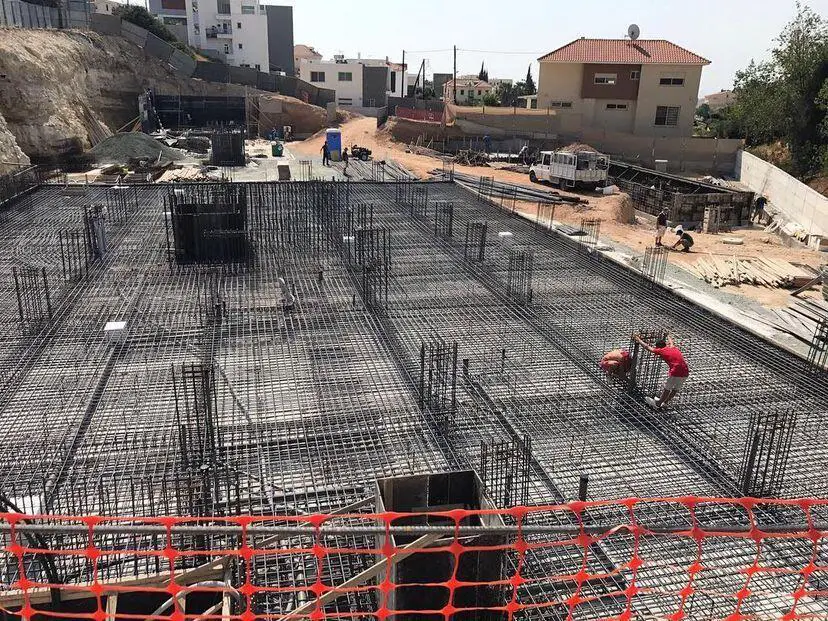
Even in cases where consolidation is a challenge or piles are employed, the flotation effect through the use of buoyancy raft (or compensated foundation) ought to be able to keep most mat settlements to a maximum of 50 to 80 mm. For all types of foundations and structures, differential settlement is a problem that deserves more serious attention. However, the use of mat foundation tends to reduce this problem.
From our previous articles, we have seen that the bending moments (6EI∆/L2) and shear forces (12EI∆/L3) in frames are dependent on the relative movement ∆ between the beam ends.
See;
Analysis of internal stresses in frames due to settlement of supports
In comparison to a spread footing (pad foundation), mat foundation due to its continuity produces somewhat reduced anticipated value of differential settlement compared to the total settlement.
| Foundation Type | Expected Maximum Settlement (mm) | Expected Differential Settlement (mm) |
| Pad foundation | 25 | 20 |
| Mat foundation | 50 | 20 |
The settlement of mat foundation depends on the rigidity of the mat, type of mat, the type of soil, the homogeneity of the soil, groundwater condition, and construction method.
To estimate both total and differential settlements, one can use computer approaches that take into account frame-foundation interaction. However, if any other than a strip from the mat is employed in a beam-on-elastic foundation type of analysis, the computing work is significant and the overall settlements will only be as accurate as the soil data.
The differential settlement of mat foundation may be arbitrarily taken as 20 mm (0.75 inches) if the total expected settlement ∆H is not more than 50 mm. Alternatively, it may be approximated using a rigidity factor Kr [see ACI Committee 336 (1988)] defined as;
Kr = EIb/EsB3
where:
EIb = flexural rigidity of the superstructure and mat
Es = modulus of elasticity of soil
B = base width of foundation perpendicular to direction of interest
ACI Committee 336 suggests that mat differential settlements are related to both the total estimated foundation settlement ∆H and the structure rigidity factor Kr about as follows:
| Kr | Differential Settlement Expected |
| 0 | 0.5 x ∆H (for long base) 0.35 x ∆H (for square base) |
| 0.5 | 0.1 x ∆H |
| > 0.5 | Rigid Mat (no differential settlement) |
However, where the net increase in pressure exceeds the current in situ pressure p’o, full settlement analyses will need to be done. Depending on the underlying soil stratification, these settlements may be immediate or consolidation settlements adjusted for OCR.
The proper design of a raft foundation should therefore strike a balance between the requirement to prevent the raft’s structure from becoming excessively rigid, and the need to limit the differential settlement of the raft and, by extension, the superstructure. Flexibility in a raft results in minimal bending moments, which saves money in the substructure.
However, this flexibility comes at the expense of relatively large differential settlement and higher costs to accommodate these movements in the superstructure, such as through joints or a flexible cladding. A raft’s stiffness reduces differential settlement but increases bending moments, which raises the cost of the raft by redistributing load.
The stiffness of the structure relative to the raft can be expressed by the following equation;
Kr = [4Ec(1 – µs2)/3Es(1 – µc2)] x (t/B)3
Where;
Kr = relative stiffness
Ec = Modulus of elasticity of concrete
Es = Modulus of elasticity of soil
µs = Poisson ratio of soil
µs = Poisson ration of concrete
t = Thickness of raft
B = Width of raft
Heave in Mat Foundation
Expansion and/or lateral flow into the excavation base, which causes the base elevation to rise, is a significant issue, especially for deep excavations in clay. Heave is the word for this occurrence, and values between 25 and 50 mm are very typical. In literature however, values up to 200 mm (or 8 inches) have been reported. When heave has occurred, settlement calculations are challenging. Theoretically, if we restore a mat pressure q0 equal to that which was previously extant, all the heave should be recovered.
In reality, this recovery doesn’t happen, or it doesn’t happen as quickly as the heave occurs. It should be anticipated that it will be extremely difficult to forecast either the overall amount of heave or how much of this will be recovered by elastic recompression if some of the heave results from a deep-seated lateral flow.
Since there are currently no valid theories for the issue of heave, estimation of the expected soil response generally requires extensive knowledge and engineering judgement where heave is encountered. A finite element of the elastic continuum computation is said to be able to solve the problem, however this claim is speculative and based on the expectation that calculations and measurements would turn out well.
The explanation is that the accuracy of a finite-element computation depends on the input parameters soil modulus of elasticity and Poisson ratio. Even if we were able to obtain a reliable initial value Es, it would still decrease during and after excavation because of the heave that is caused by the loss of confining pressure (p’o) and expansion.
Methods of Estimating the Settlement of Mat Foundation
The method of summation of partial settlements or the method of an elastic layer of finite thickness can be used to determine the settlement of raft foundations. When using the method of summation of partial settlements, the settlement is determined at a single location without taking the stiffness of the foundation into consideration.
However, in cases involving large-scale foundations, the average settlement of the foundation must be taken into account by computing the settlement at various foundation positions. The thickness of the compressed zone, which can be influenced by the size of the foundation, the applied load of higher buildings, and the soil condition, determines the settlement results of the foundation for the method of elastic layer of finite thickness.
The settlement of mat footings can be estimated using the methods developed from the theory of elasticity, assuming that they impart stresses on the ground in a manner similar to that of spread footings. The following expression (Timoshenko and Goodier, 1951) based on the theory of elasticity can be used to estimate the corner settlement of a rectangular footing with dimensions of L′ and B′;

where q is the contact stress, B′ is the least dimension of the footing, νs is the Poisson ratio of the soil, and Es is the elastic modulus of the soil. Factors I1, I2, and IF are influence factors that can be obtained from so many geotechnical engineering textbooks, in terms of the ratios N = H/B′ (H = layer thickness), M = L′/B′ (L′ = other dimension of the footing), and D/B (the foundation depth ratio).
The same expression above can be used to estimate the settlement of the footing at any point other than the corner by approximate partitioning of the footing. It must be noted that even if the footing is considered as a combination of several partitions (B′ and L′), in determining the settlement of an intermediate (non-corner) location, the depth factor, IF, is applied for the entire footing based on the ratio D/B.
Gazetas et al. (1985) considered an arbitrarily shaped rigid footing embedded in a deep homogeneous soil and proposed the following equation for the elastic settlement:
Si = (P/EuL) × (1 – vu2) × µsµembµwall
where P is total vertical load, Eu is the undrained elastic modulus of the soil, L is one-half the length of a circumscribed rectangle, vu is Poisson’s ratio for the undrained condition, and µs, µemb, and µwall are shape, embedment (trench), and side wall factors given as;
µs = 0.45(Ab/4L2)-0.38
µemb = 1 – 0.04(Df/B) × [ 1 + 1.33(Ab/4L2)]
µwall = 1 – 0.16(Aw/Ab)0.54
Ab is the actual area of the base of the foundation and Aw is the actual area of the wall in contact with the embedded portion of the footing. The length and width of the circumscribed rectangle are 2L and 2B, respectively. The dimensionless shape parameter, Ab/4L2, has the values for common footing geometry shown in the Table below;
| Footing Shape | Ab/4L2 |
| Square | 1 |
| Rectangle | B/L |
| Circular | 0.785 |
| Strip | 0 |
The equations proposed by Gazetas et al. (1985) apply to a foundation of arbitrary shape on a deep homogeneous soil. What is meant by “deep” is not clearly defined. When the thickness of the soil layer is such that 90% of the applied stresses are distributed within it, the author advises using the equations of Gazetas et al. The soil layer should be at least 2Br thick for a rectangle with actual width Br.
The accuracy of the elastic modulus is very important for any elastic equation for soils. It is standard laboratory procedure to calculate a secant Eu from unconfined compression tests or undrained triaxial tests with a deviatoric stress equal to 50% of the highest shear strength. However, it is preferable to determine Eu over the range of deviatoric stress relevant to the problem for better solution. One possible solution is to divide the soil into sublayers and use a weighted harmonic mean value of Eu.
Worked Example 1
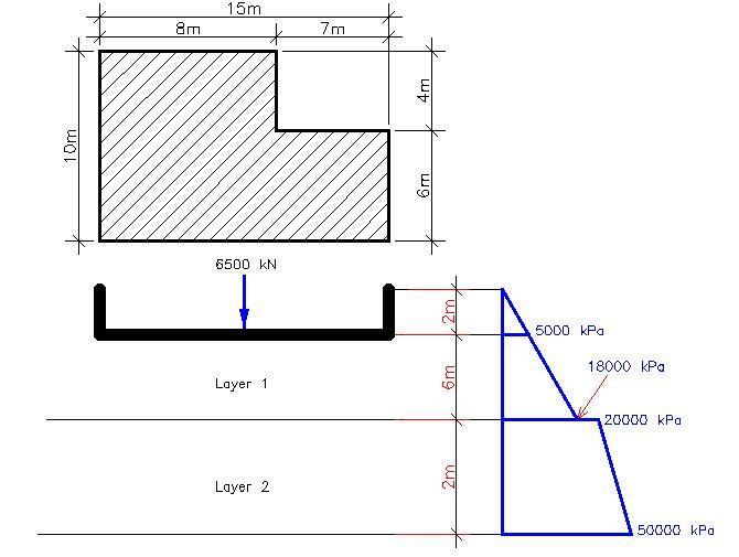
Determine the immediate settlement of the foundation shown below. The undrained elastic modulus varies with depth, as shown in the figure, and vu = 0.35.
Approach
You have to determine the length (2L) and width (2B) of a circumscribed rectangle. The undrained elastic modulus varies with depth, so you need to consider the average value of Eu for each of the layers and then find the harmonic mean. You also need to find the shape parameter Ab/4L2.
Step 1: Determine the length and width of the circumscribed rectangle.
2L = 8 + 7 = 15 m; L = 7.5 m
2B = 6 + 4 + 10 m; B = 5 m
Step 2: Determine Eu
Layer 1
Eu(ave) = (5000 + 18000)/2 = 11500 kPa
Layer 2
Eu(ave) = (20000 + 50000)/2 = 35000 kPa
Harmonic mean = (2 × 11500 × 35000)/(11500 + 35000) = 17311 kPa
Step 3: Calculate the shape parameter
Ab = (8 × 4) + (15 × 6) = 122 m2
Ab/4L2 = 122/(4 × 7.52) = 0.5422
Step 4: Find the shape, embedment, and wall factors
µs = 0.45(Ab/4L2)-0.38 = 0.45 × (0.5422)-0.38 = 0.5678
µemb = 1 – 0.04(Df/B) × [1 + 1.33(Ab/4L2)] = 1 – 0.04(2/5) × [1 + 1.33(0.5422)] = 0.972
Aw = Perimeter x depth = (10 + 8 + 4 + 7 + 6 + 15) × 2 = 100 m2
Aw/Ab = 100/122 = 0.8196
µwall = 1 – 0.16(Aw/Ab)0.54 = 1 – 0.16(0.8196)0.54 = 0.856
Step 5: Calculate the settlement
Si = (P/EuL) × (1 – vu2) × µsµembµwall = (6500/17311 × 7.5) × (1 – 0.352) × 0.5678 × 0.972 × 0.856 = 0.02075 m = 20.754 mm
Worked Example 2
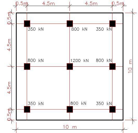
A medium dense sandy soil foundation layer is found under the mat shown below, which is underlain by a weathered bedrock at a depth of 6.0 m below the surface, estimate the average immediate settlement and the maximum differential settlement of the mat footing. Let us assume that in this case the sand is normally consolidated with SPT value of 15.
Depth of foundation = 1.0 m
Then, for an average SPT value of 15, Es is approximately given by 500(N + 15) = 15000 kPa or 15 MPa.
A Poisson’s ratio of 0.30 can also be assumed in normally consolidated sand.
The footing has been arranged such that a uniform pressure will be obtained at the base.
P = 350 + 800 + 350 + 800 + 1200 + 800 + 350 + 800 + 350 = 5800 kN
Area of base = 10 × 10 = 100 m2
Then the uniformly distributed contact stress = 5800/100 = 58 kPa
D/B for the entire footing = 1/10 = 0.1
From the chart below, for L/B = 1 and D/B = 0.1, IF = 0.85.
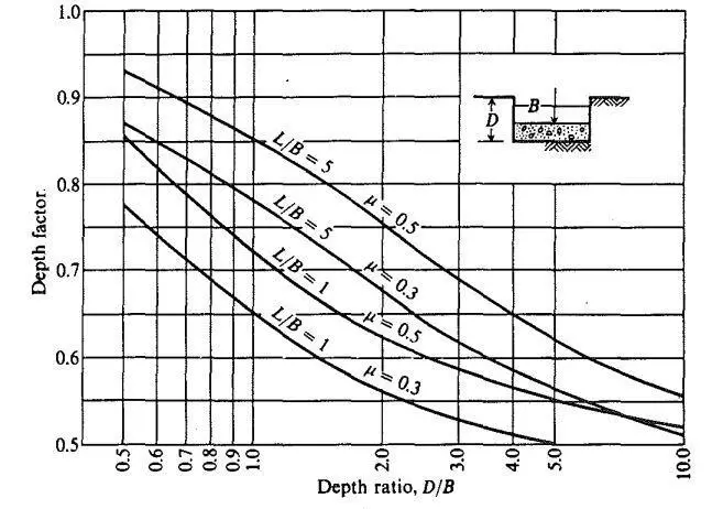
Therefore, the immediate settlement expression can be simplified to:

(1 – 2vs)/(1 – vs) = (1 – 2 × 0.3)/(1 – 0.3) = 0.571
qB’ × (1 – vs2)/E = 58B’ × (1 – 0.32)/15000 = 0.003518
Si = 58B’ × (1 – 0.32/15000) × (I1 × 0.5I2)IF = 0.00299B'(I1 × 0.571I2)
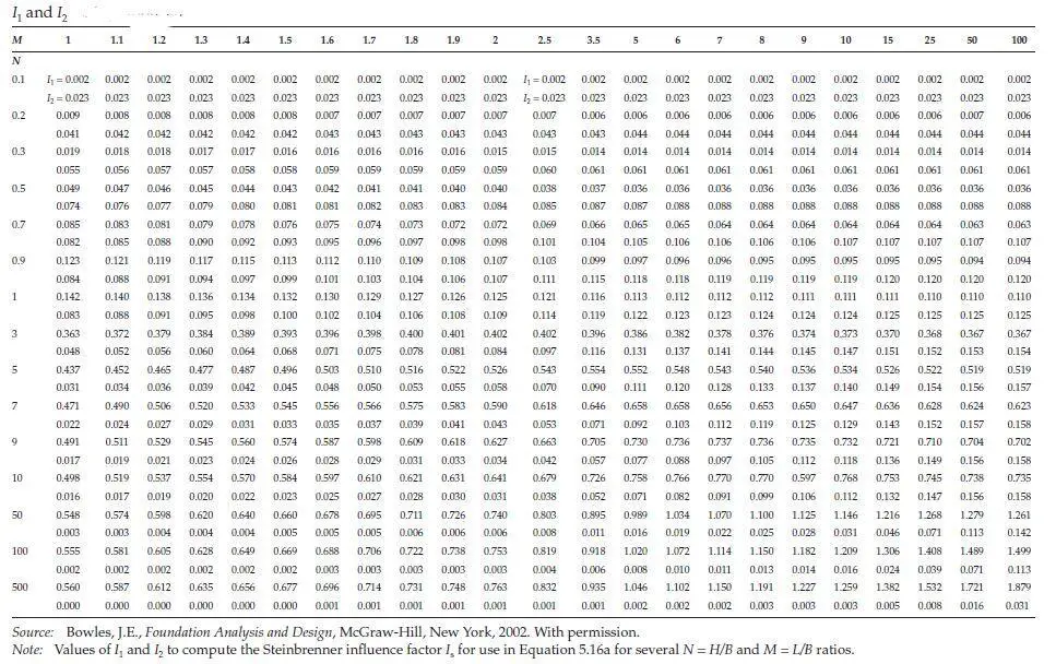
For the corner settlement
M = L/B = 1.0, N = H/B = 5/10 = 0.50
From Table above, I1 = 0.049, I2 = 0.074
Si = 0.00299B'(I1 × 0.571I2)
si = 0.00299 × 10 × [0.049 + 0.571(0.074)] = 0.0027284 m = 2.72 mm
For the center settlement
M = L/B = 5/5 = 1.0, N = H/B = 5/5 = 1.0
From Table above, I1 = 0.142, I2 = 0.083
si = {0.00299 × 5 × [0.142 + 0.571(0.083)]} × 4 = 0.01132 m = 11.325 mm
The number “4” indicates the four equal partitions required to model the center by superposition of four corners of the partitions.
Differential Settlement
Differential settlement = 11.325 – 2.712mm = 8.613 mm
Maximum angular distortion within the footing = (23.0 – 5.471)/5000 = 0.0017226 < 1/3000
Therefore, the foundation is safe from any architectural/structural damage.
Finite Element Modelling
The foundation was modelled on Staad Pro software. The soil was modelled with solid elements with the following properties;
Es = 15000 kPa
Poisson’s ratio = 0.3
The raft slab was modelled as a thin flexible plate with a full pressure of 58 kPa applied in the global vertical direction. A fixed support was applied at the base of the ground model to represent the bedrock. It should be noted that the thickness of the selected plate affects the settlement values.
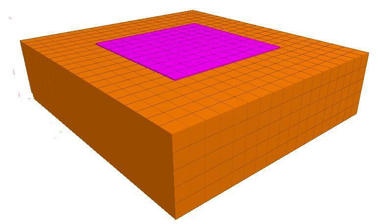
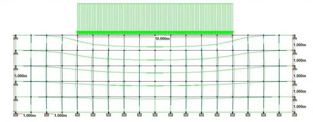
The vertical pressure distribution as a result of the loading is shown below;
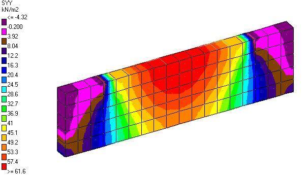
The observed settlements are shown below;
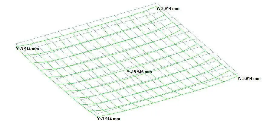
The observed corner displacements was 3.914 mm and the centre displacement was 15.546 mm.

