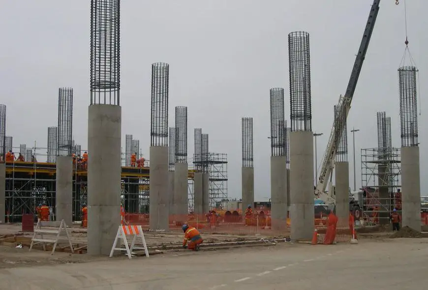
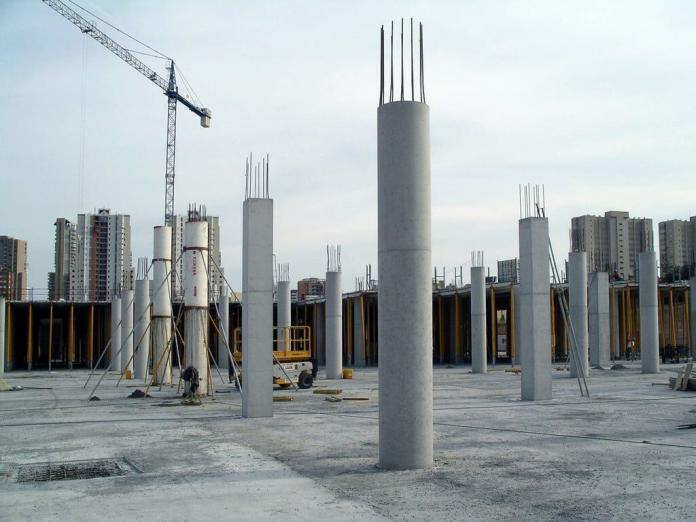
Columns are the most noticeable feature of a structure and are often used to support gravity loads transmitted from the floors or roofs of buildings. Strength, economy, adaptability, good fire resistance, and robustness are all advantages of in-situ reinforced concrete columns. During the design of columns, sound engineering judgement is often needed to balance their location, size, and shape with horizontal element spans and economy.
Circular columns are often designed for the ultimate axial load, NEd, ultimate design moment, MEd, and ultimate shear force VEd. For internal columns, moments may generally be assumed to be nominal when compared with external columns.
Due to their uniform strength in all directions, circular concrete columns are frequently employed in the design of pilings and bridge piers, and are very convenient for seismically active areas. Furthermore, it is much easier to confine the concrete using special reinforcement in circular columns than in other shapes.
Theoretical Background
When the neutral axis remains within a section, the basic equations for a section’s equilibrium under combined bending and axial load are as follows:
NRd = favbx + ∑fsAs ——- (1)
MRd = favbx(h/2 – βx) + ∑fsAs(h/2 – di) ——- (2)
In Equation (2), moments have been taken about the concrete section’s centroid. The summation signs represent a summation of all layers of reinforcement in the section. Tensile stresses must be considered negative when summing them up. di is the distance between the section’s compressive face and the ith layer of reinforcement.
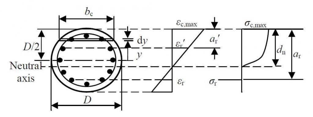
We can substitute 0.459fck for fav and 0.416 for β by assuming that the partial safety factors for the steel and concrete are 1.15 and 1.5, respectively, and that αcc is 0.85. For cases in which the neutral axis remains within the section, the resulting equations are rigorous. More complex expressions must be resolved when the entire section is in compression for the following situations;
(1) the portion of the parabolic curve cut off by the bottom of the section and
(2) the reduction in the ultimate strain at the compressive face
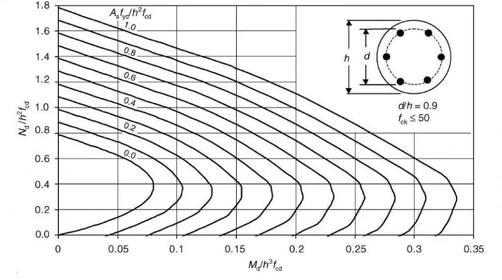
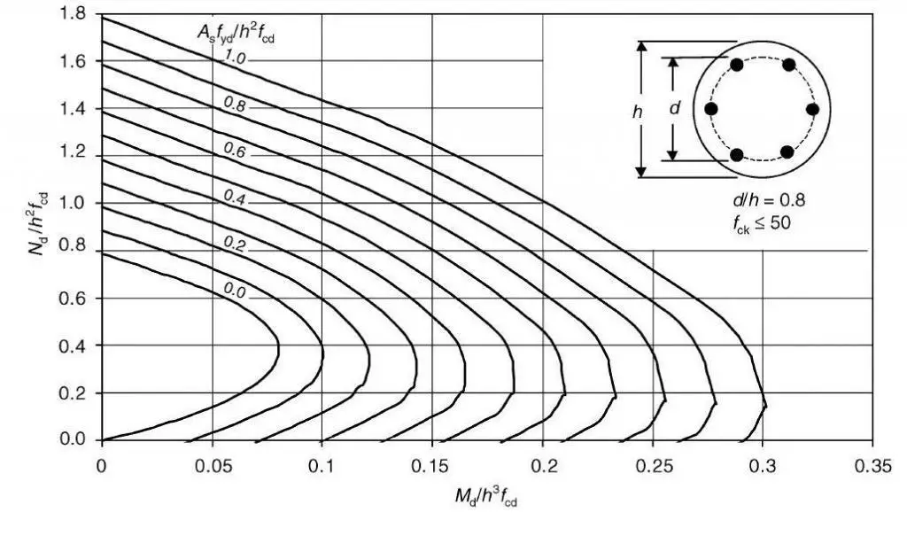
Additionally, for situations when the concrete strength is greater than 50 N/mm2, more complicated equations are required. Because of how complex the resulting equations are, it is inappropriate to present them here. Using design charts is an easier method.
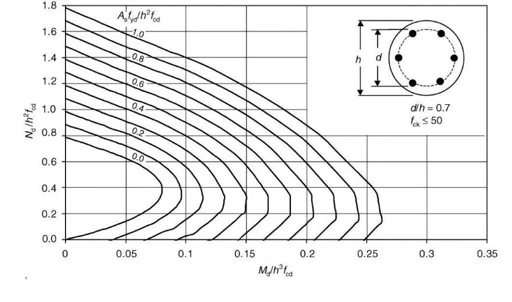
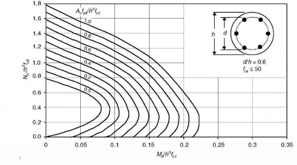
Some design charts for circular columns are given below. Since six reinforcing bars are the minimum that can be employed in a circular section, this is the assumption made while drawing the charts. It is discovered that no specific arrangement of reinforcement in relation to the axis of bending will always result in minimal strength. As a result, the charts are produced to provide a lower bound envelope to the interaction diagrams for different bar arrangements.
Design Example of RC Circular Columns
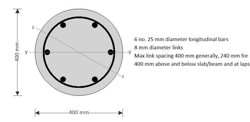
Verify the resistance of 6H25 bars to withstand the loads in a column of a high-rise building in accordance with EN1992-1-1 incorporating Corrigendum January 2008 and the UK national annex. The design information is as follows;
Height of column = 5m
fck = C25/30
fyk = 500 MPa
Diameter of column = 400 mm
Design axial load; NEd = 1500.0 kN
Moment about y-axis at top; Mtopy = 66.0 kNm
Moment about y-axis at bottom; Mbtmy = 32.0 kNm
Moment about z-axis at top; Mtopz = 25.0 kNm
Moment about z-axis at bottom; Mbtmz = 5.5 kNm
Column geometry
Overall diameter; h = 400 mm
Clear height between restraints about y-axis; ly = 5000 mm
Clear height between restraints about z-axis; lz = 5000 mm
Stability in the z direction; Braced
Stability in the y direction; Braced
Concrete details
Concrete strength class; C25/30
Partial safety factor for concrete (2.4.2.4(1)); γC = 1.50
Coefficient αcc (3.1.6(1)); αcc = 0.85
Maximum aggregate size; dg = 20 mm
Reinforcement details
Nominal cover to links; cnom = 35 mm
Longitudinal bar diameter; φ= 25 mm
Link diameter; φv = 8 mm
Total number of longitudinal bars; N = 6
Area of longitudinal reinforcement; As = N × (π × φ2 / 4) = 2945 mm2
Characteristic yield strength; fyk = 500 N/mm2
Partial safety factor for reinft (2.4.2.4(1)); γS = 1.15
Modulus of elasticity of reinft (3.2.7(4)); Es = 200 kN/mm2
Fire resistance details
Fire resistance period; R = 60 min
Exposure to fire; Exposed on more than one side
Ratio of fire design axial load to design resistance; mfi = 0.70
Axial load and bending moments from frame analysis
Design axial load; NEd = 1500.0 kN
Moment about y axis at top; Mtopy = 66.0 kNm
Moment about y axis at bottom; Mbtmy = 32.0 kNm
Moment about z axis at top; Mtopz = 25.0 kNm
Moment about z axis at bottom; Mbtmz = 5.5 kNm
Beam/slab concrete strength class; C25/30
Beams/slabs providing rotational restraint about y axis
Depth on side A; hA1y = 500 mm
Width on side A; bA1y = 300 mm
Length on side A; lA1y = 4500 mm
Depth on side B; hB1y = 500 mm
Width on side B; bB1y = 300 mm
Length on side B; lB1y = 6000 mm
Beams providing rotational restraint about z axis
Depth on side A; hA1z = 500 mm
Width on side A; bA1z = 300 mm
Length on side A; lA1z = 3500 mm
Depth on side B; hB1z = 500 mm
Width on side B; bB1z = 300 mm
Length on side B; lB1z = 3500 mm
Relative flexibility end 2 for buckling about y axis; k2y = 1000.000
Relative flexibility end 2 for buckling about z axis; k2z = 1000.000
Calculated column properties
Area of concrete; Ac = π × h2 / 4 = 125664 mm2
Column characteristic comp. cylinder strength; fck = 25 N/mm2
Column design comp. strength (3.1.6(1)); fcd = acc × fck / γC = 14.2 N/mm2
Column mean value of cyl. strength (Table 3.1); fcm = fck + 8 MPa = 33.0 N/mm2
Column secant modulus of elasticity (Table 3.1); Ecm = 22000 MPa × (fcm / 10 MPa)0.3 = 31.5 kN/mm2
Beam/slab characteristic comp. cylinder strength; fck_b = 25 N/mm2
Beam/slab mean value of cyl. strength (3.1.6(1)); fcm_b = fck_b + 8 MPa = 33.0 N/mm2
Beam/slab secant mod. of elasticity (Table 3.1); Ecm_b = 22000 MPa × (fcm_b / 10 MPa)0.3 = 31.5 kN/mm2
Rectangular stress block factors
Depth factor (3.1.7(3)); λsb = 0.8
Stress factor (3.1.7(3)); η = 0.9
Strain limits
Compression strain limit (Table 3.1); εcu3 = 0.00350
Pure compression strain limit (Table 3.1); εc3 = 0.00175
Design yield strength (3.2.7(2)); fyd = fyk / γS = 434.8 N/mm2
Check nominal cover for fire and bond requirements
Min. cover reqd for bond (to links) (4.4.1.2(3)); cmin,b = max(φv, φ – φv) = 17 mm
Min axis distance for fire (EN1992-1-2 T 5.2a); afi = 40 mm
Allowance for deviations from min cover (4.4.1.3); Dcdev = 10 mm
Min allowable nominal cover; cnom_min = max(afi – φ/2 – φv, cmin,b + Dcdev) = 27.0 mm
PASS – the nominal cover is greater than the minimum required
Effective depth and inertia of bars for bending about y axis
For the purposes of determining the bending capacity and interaction diagrams in this calculation, bending about the y axis is taken to be when there are two furthest equidistant bars on each side of the column centreline. Bending about the z axis is taken to be when there is one furthest bar on each side of the column centreline.
Area per bar; Abar = π × φ2 / 4 = 491 mm2
Radial dist from column centre to longitudinal bar; rl = h/2 – cnom – φv – φ/2 = 144.5 mm
Subtended angle between adjacent bars; α = (360 deg) / N = 60.0 deg
Layer 1; dy1 = h/2 + rl × cos(α/2) = 325.1 mm
2nd moment of area of reinft about y axis; Iy1 = 2 × Abar × (dy1 – h/2)2 = 1537 cm4
Layer 2; dy2 = h / 2 + rl × cos[(2 – 1) × a + a/2] = 200.0 mm
2nd moment of area of reinft about y axis; Iy2 = 2 × Abar × (dy2 – h/2)2 = 0 cm4
Layer 3; dy3 = h / 2 + rl × cos[(3 – 1) × a + a/2] = 74.9 mm
2nd moment of area of reinft about y axis; Iy3 = 2 × Abar × (dy3 – h/2)2 = 1537 cm4
Total 2nd moment of area of reinft about y axis; Isy = 3075 cm4
Radius of gyration of reinft about y axis; isy = √(Isy / As) = 102 mm
Effective depth about y axis (5.8.8.3(2)); dy = h / 2 + isy = 302 mm
Effective depth of bars for bending about z axis
Layer 1 (tension face); dz1 = h / 2 + rl = 344.5 mm
2nd moment of area of reinft about z axis; Iz1 = Abar × (dz1 – h / 2)2 = 1025 cm4
Layer 2; dz2 = h / 2 + rl × cos[(2 – 1) × a] = 272.3 mm
2nd moment of area of reinft about z axis; Iz2 = 2 × Abar × (dz2 – h/2)2 = 512 cm4
Layer 3; dz3 = h / 2 + rl × cos[(3 – 1) × a] = 127.8 mm
2nd moment of area of reinft about z axis; Iz3 = 2 × Abar × (dz3 – h/2)2 = 512 cm4
Layer 4; dz4 = h / 2 + rl × cos[(4 – 1) × a] = 55.5 mm
2nd moment of area of reinft about z axis; Iz4 = 1 × Abar × (dz4 – h/2)2 = 1025 cm4
Total 2nd moment of area of reinft about z axis; Isz = 3075 cm4
Radius of gyration of reinforcement about z axis; isz = √(Isz / As) = 102 mm
Effective depth about z axis (5.8.8.3(2)); dz = b / 2 + isz = 302 mm
Relative flexibility at end 1 for buckling about y axis
Second moment of area of column; Iy = π × h4 / 64 = 125664 cm4
Second moment of area of beam on side A; IA1y = bA1y × hA1y3 / 12 = 312500 cm4
Second moment of area of beam on side B; IB1y = bB1y × hB1y3 / 12 = 312500 cm4
Relative flexibility (PD6687 cl. 2.10); k1y = max(0.1, (Ecm × Iy / ly) / [2 × Ecm_b × (IA1y/lA1y + IB1y/lB1y)]) = 0.103
Relative flexibility end 2 for buckling about y axis; k2y = 1000.000
Relative flexibility at end 1 for buckling about z axis
Second moment of area of column; Iz = π × h4 / 64 = 125664 cm4
Second moment of area of beam on side A; IA1z = bA1z × hA1z3 / 12 = 312500 cm4
Second moment of area of beam on side B; IB1z = bB1z × hB1z3 / 12 = 312500 cm4
Relative flexibility (PD6687 cl. 2.10); k1z = max(0.1, (Ecm × Iz / lz) / [2 × Ecm_b × (IA1z/lA1z + IB1z/lB1z)]) = 0.100
Relative flexibility end 2 for buckling about z axis; k2z = 1000.000
Calculated effective length (cl. 5.8.3.2)
Eff. length about y axis (braced) (5.8.3.2(3));
l0y = 0.5 × ly × [(1 + k1y/(0.45+k1y)) × (1 + k2y/(0.45+k2y))]0.5 = 3851 mm
Eff. length about z axis (braced) (5.8.3.2(3));
l0z = 0.5 × lz × [(1 + k1z/(0.45+k1z)) × (1 + k2z/(0.45+k2z))]0.5 = 3843 mm
Column slenderness about y axis
Radius of gyration; iy = h / 4 = 10.0 cm
Slenderness ratio (5.8.3.2(1)); ly = l0y / iy = 38.5
Column slenderness about z axis
Radius of gyration; iz = h / 4 = 10.0 cm
Slenderness ratio (5.8.3.2(1)); lz = l0z / iz = 38.4
Design bending moments
Frame analysis moments about y axis combined with moments due to imperfections (cl. 5.2 & 6.1(4))
Ecc. due to geometric imperfections (y axis); eiy = l0y /400 = 9.6 mm
Min end moment about y axis; M01y = min(abs(Mtopy), abs(Mbtmy)) + eiy × NEd = 46.4 kNm
Max end moment about y axis; M02y = max(abs(Mtopy), abs(Mbtmy)) + eiy × NEd = 80.4 kNm
Slenderness limit for buckling about y axis (cl. 5.8.3.1)
Factor A; A = 0.7
Mechanical reinforcement ratio; w = As × fyd / (Ac × fcd) = 0.719
Factor B; B = √(1 + 2 × w) = 1.562
Moment ratio; rmy = M01y / M02y = 0.577
Factor C; Cy = 1.7 – rmy = 1.123
Relative normal force; n = NEd / (Ac × fcd) = 0.843
Slenderness limit; llimy = 20 × A × B × Cy / √(n) = 26.7
ly > llimy – Therefore, second order effects must be considered
Frame analysis moments about z axis combined with moments due to imperfections (cl. 5.2 & 6.1(4))
Ecc. due to geometric imperfections (z axis); eiz = l0z /400 = 9.6 mm
Min end moment about z axis;
M01z = min(abs(Mtopz), abs(Mbtmz)) + eiz × NEd = 19.9 kNm
Max end moment about z axis;
M02z = max(abs(Mtopz), abs(Mbtmz)) + eiz × NEd = 39.4 kNm
Slenderness limit for buckling about y axis (cl. 5.8.3.1)
Factor A; A = 0.7
Mechanical reinforcement ratio; w = As × fyd / (Ac × fcd) = 0.719
Factor B; B = √(1 + 2 × w) = 1.562
Moment ratio; rmz = M01z / M02z = 0.505
Factor C; Cz = 1.7 – rmz = 1.195
Relative normal force; n = NEd / (Ac × fcd) = 0.843
Slenderness limit; llimz = 20 × A × B × Cz / √(n) = 28.5
lz > llimz – Second order effects must be considered
Local second order bending moment about y axis (cl. 5.8.8.2 & 5.8.8.3)
Relative humidity of ambient environment; RH = 50 %
Column perimeter in contact with atmosphere; u = 1257 mm
Age of concrete at loading; t0 = 28 day
Parameter nu; nu = 1 + w = 1.719
Approx value of n at max moment of resistance; nbal = 0.4
Axial load correction factor; Kr = min(1.0 , (nu – n) / (nu – nbal)) = 0.665
Reinforcement design strain; eyd = fyd / Es = 0.00217
Basic curvature; curvebasic_y = eyd / (0.45 × dy) = 0.0000160 mm-1
Notional size of column; h0 = 2 × Ac / u = 200 mm
Relative humidity factor (Annex B.1(1)); φRH = 1 + [(1 – RH / 100%) / (0.1 mm-1/3 × (h0)1/3)] = 1.855
Concrete strength factor (Annex B.1(1)); βfcm = 16.8 × (1 MPa)1/2 / √(fcm) = 2.925
Concrete age factor (Annex B.1(1)); bt0 = 1 / (0.1 + (t0 / 1 day)0.2) = 0.488
Notional creep coefficient (Annex B.1(1)); φ0 = φRH × βfcm × βt0 = 2.650
Final creep development factor; (at t = ∞); βc∞ = 1.0
Final creep coefficient (Annex B.1(1)); fφ∞ = φ0 × βc∞ = 2.650
Ratio of SLS to ULS moments; rMy = 0.80
Effective creep ratio; φefy = φ∞ × rMy = 2.120
Factor b; by = 0.35 + fc /200 – λy/150 = 0.218
Creep factor; Kfy = max(1.0 , 1 + by × φefy) = 1.463
Modified curvature; curvemod_y = Kr × Kfy × curvebasic_y = 0.0000155 mm-1
Curvature distribution factor; c = 10
Deflection; e2y = curvemod_y × l0y2 / c = 23.0 mm
Nominal 2nd order moment;M2y = NEd × e2y = 34.6 kNm
Design bending moment about y axis (cl. 5.8.8.2 & 6.1(4))
Equivalent moment from frame analysis;
M0ey = max(0.6 × M02y + 0.4 × M01y, 0.4 × M02y) = 66.8 kNm
Design moment;
MEdy = max(M02y, M0ey + M2y, M01y + 0.5×M2y, NEd × max(h/30, 20 mm))
MEdy = 101.4 kNm
Local second order bending moment about z axis (cl. 5.8.8.2 & 5.8.8.3)
Basic curvature; curvebasic_z = eyd / (0.45 × dz) = 0.0000160 mm-1
Ratio of SLS to ULS moments; rMz = 0.80
Effective creep ratio (5.8.4(2)); φefz = φ∞ × rMz = 2.120
Factor b; bz = 0.35 + fck / 200 MPa – lz / 150 = 0.219
Creep factor; Kfz = max(1.0 , 1 + bz × fefz) = 1.464
Modified curvature; curvemod_z = Kr × Kfz × curvebasic_z = 0.0000156 mm–
Curvature distribution factor; c = 10
Deflection; e2z = curvemod_z × l0z2 / c = 23.0 mm
Nominal 2nd order moment; M2z = NEd × e2z = 34.5 kNm
Design bending moment about z axis (cl. 5.8.8.2 & 6.1(4))
Equivalent moment from frame analysis;
M0ez = max(0.6 × M02z + 0.4 × M01z, 0.4 × M02z) = 31.6 kNm
Design moment;
MEdz = max(M02z, M0ez + M2z, M01z + 0.5×M2z, NEd × max(b/30, 20 mm))
MEdz = 66.1 kNm
Resultant design bending moment for a circular column
Resultant design moment; MEd = √(MEdy2 + MEdz2) = 121.0 kNm
Moment capacity about y axis with axial load NEd
Moment of resistance of concrete
By iteration:-
Position of neutral axis; y = 289.8 mm
Depth of stress block; dsby = min(lsb × y , h) = 231.8 mm
Area of concrete in compression; Asby = 75498 mm2
Concrete compression force (3.1.7(3));Fyc = h × fcd × Asby = 962.6 kN
Centroid of concrete compression from column cl; ysby = 68.0 mm
Moment of resistance; MRdyc = Fyc × ysby = 65.4 kNm
Moment of resistance of reinforcement
Strain in layer 1; εy1 = εcu3 × (1 – dy1 / y) = -0.00043
Stress in layer 1; σy1 = max(-1×fyd, Es × εy1) = -85.5 N/mm2
Force in layer 1;Fy1 = 2 × Abar × sy1 = -83.9 kN
MRdy1 = Fy1 × (h / 2 – dy1) = 10.5 kNm
Strain in layer 2; εy2 = εcu3 × (1 – dy2 / y) = 0.00108
Stress in layer 2; σy2 = min(fyd, Es × εy2) – h × fcd = 204.1 N/mm2
Force in layer 2; Fy2 = 2 × Abar × sy2 = 200.4 kN
Moment of resistance of layer 2; MRdy2 = Fy2 × (h/2 – dy2) = 0.0 kNm
Strain in layer 3; εy3 = εcu3 × (1 – dy3 / y) = 0.00260
Stress in layer 3; σy3 = min(fyd, Es × εy3) – h × fcd = 422.0 N/mm2
Force in layer 3; Fy3 = 2 × Abar × sy3 = 414.3 kN
Moment of resistance of layer 3; MRdy3 = Fy3 × (h/2 – dy3) = 51.8 kNm
Resultant concrete/steel force; Fy = 1493.3 kN
PASS – This is within half of one percent of the applied axial load
Combined moment of resistance
Moment of resistance about y axis; MRdy = 127.8 kNm
Moment capacity about z axis with axial load NEd
Moment of resistance of concrete
By iteration:-
Position of neutral axis; z = 287.0 mm
Depth of stress block; dsbz = min(lsb × z , h) = 229.6 mm
Area of concrete in compression; Asbz = 74628 mm2
Concrete compression force (3.1.7(3)); Fzc = h × fcd × Asbz = 951.5 kN
Centroid of concrete compression from column cl; ysbz = 69.1 mm
Moment of resistance; MRdzc = Fzc × ysbz = 65.8 kNm
Moment of resistance of reinforcement
Strain in layer 1; εz1 = εcu3 × (1 – dz1 / z) = -0.00070
Stress in layer 1; σz1 = max(-1×fyd, Es × εz1) = -140.2 N/mm2
Force in layer 1; Fz1 = 1 × Abar × sz1 = -68.8 kN
Moment of resistance of layer 1; MRdz1 = Fz1 × (h / 2 – dz1) = 9.9 kNm
Strain in layer 2; εz2 = εcu3 × (1 – dz2 / z) = 0.00018
Stress in layer 2; σz2 = min(fyd, Es × εz2) = 36.0 N/mm2
Force in layer 2; Fz2 = 2 × Abar × sz2 = 35.3 kN
Moment of resistance of layer 2; MRdz2 = Fz2 × (h / 2 – dz2) = -2.6 kNm
Strain in layer 3; εz3 = εcu3 × (1 – dz3 / z) = 0.00194
Stress in layer 3; σz3 = min(fyd, Es × εz3) – h × fcd = 375.7 N/mm2
Force in layer 3; Fz3 = 2 × Abar × sz3 = 368.8 kN
Moment of resistance of layer 3; MRdz3 = Fz3 × (h/2 – dz3) = 26.6 kNm
Strain in layer 4; εz4 = εcu3 × (1 – dz4/z) = 0.00282
Stress in layer 4; σz4 = min(fyd, Es × εz4) – h × fcd = 422.0 N/mm2
Force in layer 4; Fz4 = 1 × Abar × sz4 = 207.2 kN
Moment of resistance of layer 4; MRdz4 = Fz4 × (h/2 – dz4) = 29.9 kNm
Resultant concrete/steel force; Fz = 1494.0 kN
PASS – This is within half of one percent of the applied axial load
Combined moment of resistance
Moment of resistance about z axis; MRdz = 129.8 kNm
Minimum moment capacity with axial load NEd
Minimum moment capacity; MRd = min(MRdz, MRdy) = 127.8 kNm
PASS – The moment capacity exceeds the resultant design bending moment
Summary
| Description | Unit | Provided | Required | Utilisation | Result |
| Moment capacity (y) | kNm | 127.79 | 101.41 | 0.79 | PASS |
| Moment capacity (z) | kNm | 129.76 | 66.06 | 0.51 | PASS |
| Combined capacity | kNm | 127.79 | 121.03 | 0.95 | PASS |
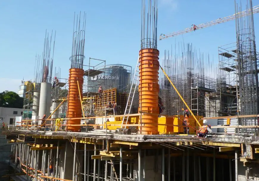





Jacketing concrete pad,column,beam,slab in construction