To transfer structural load to a capable bearing strata, micropiles, often referred to as minipiles, needle piles, or pin piles, are employed in practically any type of ground. Micropiles are slender columns of deep foundations with relatively small diameter and low load bearing capacity that are installed relatively close to each other. They are constructed using high strength steel casing or threaded pipes, and may be filled with concrete grouts and steel reinforcement. Sometimes, micropiles are also constructed using concrete or timber.
Micropiles were initially low-capacity, small-diameter piles (2 to 4 in., or 5 to 10 cm). However, improvements in drilling technology have led to design load capacities and diameters exceeding 300 tonnes and 250 mm respectively. In sites with low headroom and restricted access, micropiles are frequently used.
Although there are many uses for micropiles, they are most frequently utilised to support new or existing foundations in places with little headroom and difficult access. Other uses of micropiles are to provide structural support, underpin foundations to eliminate settlement, improve soil and slope stability, and transfer loads to a stable soil strata.
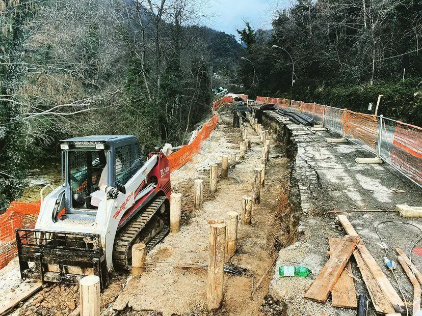
Applicable soil types
Micropiles can be employed in almost any subsurface soil or rock since they can be inserted using drilling equipment and combined with various grouting procedures to form the bearing element. The bearing soil or rock will determine their load carrying capacity. The absence of necessary overhead or lateral site constraints that would prevent installations requiring considerably larger equipment is one of the major benefits of using micropiles.
Micropiles can offer large compressional capacity as well as good tensile capacity. According to the industry (www.rembco.com), micropiles have a working capacity of up to 2200 kN (250 tonnes). According to (www.keller.com), capacities of about 500 tonnes have also been achieved. When micropiles are pressure-grouted in place for higher capacity, the relative density and lateral pressure of the surrounding soil (if compressible) is increased, thereby leading to considerably higher shaft resistance.
Traditionally, micropiles are installed in predrilled holes that are filled with concrete.
Equipment
Typically, the micropile shaft is bored or hammered into position. A drill rig or small pile driving hammer mounted on a base unit is therefore necessary. It is necessary to have the proper grout mixing and pumping equipment since the pipe is filled with cement grout. The proper grouting equipment is also necessary if compaction grout or jet grout will be used to produce the bearing element.
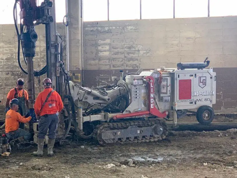
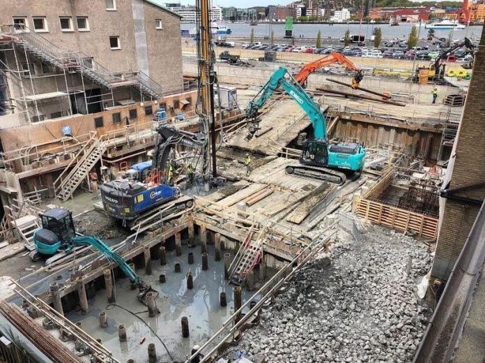
Micropiles typically require compact small-sized equipment that can be used in confined spaces with limited access. The application of micropiles has a very broad range; it can be carried out in spaces with little vertical clearance, such as basements and under bridge structures. The interiors of commercial structures, tiny tunnels, mountain paths, rice fields, mountainous forested areas, steep slopes, and other places are some other examples of important sites where the micropiles can be installed. Additionally, micropiles can be inserted through existing foundations and used to support buildings as well as fix broken foundations.
Procedures for construction
Typically, the micropile shaft is either driven or drilled into position. Some sort of bearing element must be created if the specified pile capacity cannot be reached in end bearing and side friction along the pipe. This could entail drilling a rock socket, filling it with grout, and installing a full length, high-strength threaded bar if the tip is covered in rock. Compaction grouting or jet grouting can be carried out below the bottom of the pipe if it is surrounded or covered by soil. Additionally, the pipe can be partially withdrawn while being filled with grout that is pressured to produce a bond zone.
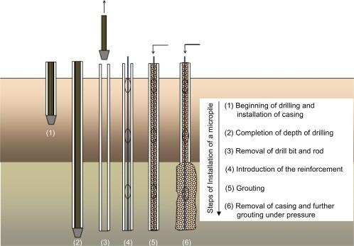
The figure above shows the micropile installation procedure. A drilling technique that is appropriate for the soil/site conditions is used to drill boreholes with casings. Following removal of the drilling rod and tools, reinforcement bars—typically corrosion-resistant steel bars—are next placed into the boreholes. Next, grouting is carried out sequentially under pressure as the casing is gradually removed.
Materials for construction of micropiles
A steel rod or pipe often makes up the micropile. The bond zone and pipe fill are frequently created using grout made of Portland cement. Another typical item is a full-length steel threaded bar made of grade 40 (275 N/mm2) to 150 ksi (1035 N/mm2) steel. The micropile may occasionally be nothing more than a reinforced concrete grout column.
Design of micropiles
Three components make up the design of micropiles;
- the connection to the current or proposed structure,
- the pile shaft that transmits the load to the bearing zone, and
- the bearing element that sends the load to the layer of soil or rock that is carrying the load.
The piling section is designed using a typical structural analysis. In the event that a grouted friction socket is intended, the Table below can be used to determine the diameter and length of the socket. Bond lengths more than 30 feet (9.2 metres) do not improve the capacity of the piles.
| Soil/Rock Description | SPT N value (blows/ft) | Grout Bond with Soil/Rock (ksf) |
| Nonpressure grouted | ||
| Silty clay | 3—6 | 0.5—1.0 |
| Sandy clay | 3—6 | 0.7—1.0 |
| Medium clay | 4-8 | 0.75—1.25 |
| Firm clay or stiffer | >8 | 1.0—1.5 |
| Sands Soft shales | 10-30 | 2—4 5—15 |
| Slate and hard shales | 15—28 | |
| Sandstones | 15—35 | |
| Soft limestone | 15—33 | |
| Hard limestone | 20—35 | |
| Pressure grouted | ||
| Medium dense sand | 3.5 – 6.5 | |
| Dense sand | 5.5 – 8.5 | |
| Very dense sand | 8-12 |
Micropiles can be divided into two categories based on design uses. The first category consists of micropiles that are loaded laterally or axially. This collection of micropiles distributes structural loads to the competent strata beneath the foundation (for example, through the underpinning of structures), or they can be utilised to stop the movement of failure planes (i.e. stabilisation of slopes).
The second category consists of micropiles that are utilised to create a reinforced soil composite, which strengthens the soil mass. However, based on the grouting techniques, micropiles can also be divided into four groups (Groups A, B, C, and D).
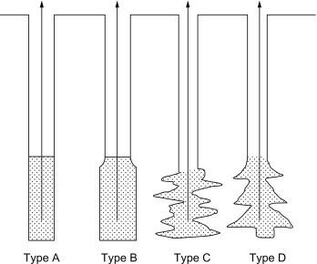
The grouting for the group A micropiles is set under gravity. In group B, grout is injected under pressure into the hole, but the pressure is constrained to prevent hydrofracturing of the nearby soil. Group C micropiles are installed in two steps: first, a primary grout is pressure-applied to hydrofracture the surrounding ground, and then, just before the main grout sets, a secondary grout is injected through a manchette tube. The primary grout is injected after the primary grout has hardened in group “D” micropiles, which are similar to group “C” micropiles.
Quality control and assurance
During the construction of the micropile, the drilling penetration rate can be monitored as an indication of the stratum being drilled. Grout should be sampled for subsequent compressive strength testing. The piles verticality and length should also be monitored and documented. A test pile is constructed at the beginning of the work and load tested to 200% of the design load in accordance with the standard specification ASTM D 1143.

