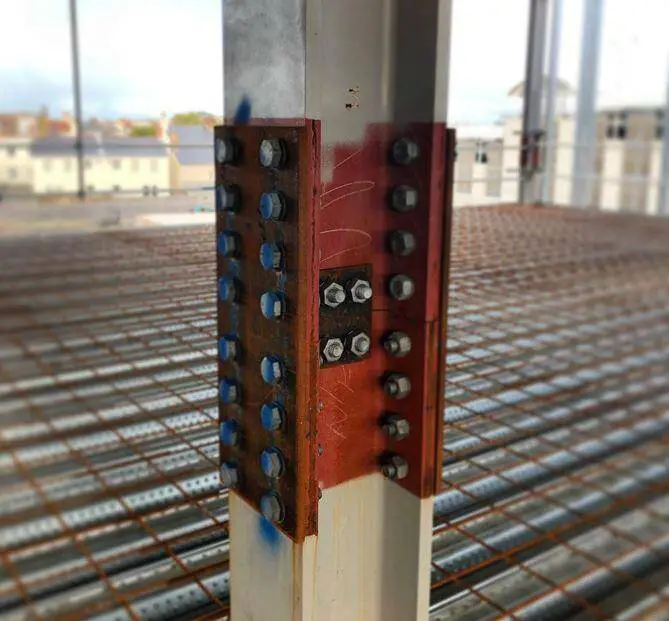
Column splice connection design involves joining two or more column sections to create a longer column or to provide additional strength. It is used when the length of a column is too long to be fabricated as a single piece. They are also used for connecting columns of different sections as a building goes higher. Similar to beam splices, column splices are typically designed to transfer axial load, shear, and moment.
Properly designed column splice connections are important in ensuring easier buildability, transportation, handling, and maintaining the overall stability and safety of various construction projects in steel structures. The primary function of a column splice connection is to transfer axial loads and moments between the connected column sections. The design should effectively distribute the applied loads through the connection without compromising the structural integrity.
In this article, we will explore the design of bolted column splice connection.
Types of Column Splices
There are two main types of column splices: bearing splices and non-bearing splices. Bearing splices rely on full bearing contact between the two column sections to transfer the axial load. In this case, the loads from the upper column are directly transferred to the lower column through the use of division plates or direct contact between the two sections.
Non-bearing splices use bolts or welds to transfer the axial load. In this case, there is no bearing between the interconnected columns and they are usually detailed with a gap in between the column stacks.
Design of column Splices
The design of a column splice must consider the following factors:
- The type of splice (bearing or non-bearing)
- The size and strength of the column sections
- The axial load, shear, and moment applied to the splice
- The material properties of the column sections and the splice plates
Design Example
Design a column splice connection for two similar column sections (UC 254x254x89) subjected to an axial dead load of 528kN and a design moment of 178 kN. The ends are not prepared for contact in bearing.
Section Details
Upper Stanchion; UC 254x254x89 (S275)
Lower Stanchion; UC 254x254x89 (S275)
Flange splice plate; 120 mm × 690 mm × 15 mm (S275)
Flange plate bolts; M22 (Grade 8.8 Black Bolts)
Web splice plate; 137 mm × 390 mm × 15 mm (S275)
Web plate bolts; M22 (Grade 8.8 Black Bolts)
Splice Details
Flange plates
Number of bolt rows above and below splice; nfpr = 4
Number of bolt columns above and below splice; nfpc = 2
Dist from end of upper column to first row of bolts; eucfend = 60 mm
Dist from end of lower column to first row of bolts; elcfend = 60 mm
Bolt pitch; pfpb = 75 mm
Distance from outer bolts to plate end; efpend = 60 mm
Web plates
number of bolt rows above and below splice; nwpr = 2
number of bolt columns above and below splice; nwpc = 2
Dist from end of upper column to first row of bolts; eucwend = 60 mm
Dist from end of lower column to first row of bolts; elcwend = 60 mm
Bolt pitch; pwpb = 75 mm
Distance from outer bolts to plate end; ewpend = 60 mm

Loading Details
Axial compressive force due to dead load; Fcd = 528.0 kN
Moment on splice; M = 178.0 kNm
Design Loading
Design load;
Ft = max(0 kN, abs(M) / min(Du – 2Tu – tfp, Dl – 2Tl – tfp) – Fcd / 2) = 580.8 kN
Check 1 – recommended detailing requirements – column splice, flange plates on inside
Upper Column
Overall depth; Du = 260 mm
Overall width; Bu = 256 mm
Flange thickness; Tu = 17.3 mm
Web thickness; tu = 10.3 mm
Root radius; ru = 12.7 mm
Lower Column
Overall depth; Dl = 260 mm
Overall width; Bl = 256 mm
Flange thickness; Tl = 17.3 mm
Web thickness; tl = 10.3 mm
Root radius; rl = 12.7 mm
Flange Plates
Upper projection;
Lfpu = eucfend + (nfpr – 1) × pfpb + efpend = 345 mm
Lower projection;
Lfpl = elcfend + (nfpr – 1) × pfpb + efpend = 345 mm
Detailing Requirements
The upper projection of the flange plate meets the detailing requirements
Lower projection of flange plate meets detailing requirements
The width of the flange plate meets the detailing requirements
The thickness of flange plates meets the detailing requirements
The width of web plates meets the detailing requirements
Flange plate packing;
tfpack = abs((Du / 2 – Tu) – (Dl/2 – Tl)) = 0.0 mm
Web plate packing;
twpack = abs(tu – tl) / 2 = 0.0 mm
Sufficient web plate bolts provided
Bearing plate not required
Check 2 – the presence of tension due to axial load and bending moment – internal
Tension Force;
Ft = M / min(Du – 2Tu – tfp, Dl – 2Tl – tfp) – Fcd / 2 = 580.8 kN
Check 3 – tensile capacity of flange cover plate – internal
Grade of cover plate;
pyfp = 275 N/mm2
Net area of flange cover plates (one flange);
Anetfp = 2(dfp – nfpc / 2Dhfb ) × tfp = 2880 mm2
Net area coefficient;
Kefp = 1.2
Gross area of flange cover plates (one flange);
Agrossfp = 2dfptfp = 3600 mm2
Design area of flange cover plates (one flange);
Afp = min(Kefp × Anetfp, Agrossfp) = 3456 mm2
Tensile capacity;
Ptfp = pyfp × Afp = 950.4 kN
Utilisation factor;
Ucheck3 = Ft / Ptfp = 0.611
Tension capacity of flange cover plate: PASS
Check 4 – Shear capacity of bolt group connecting flange cover plate to column flange
Grade of bolts;
pbsfp = 460 N/mm2
Shear capacity of top pair of bolts;
Psfb1 = min(Psfb, 0.5 × efpend × tfp × pbsfp) = 113.6 kN
Shear capacity of other bolts; Psfb = 113.6 kN
Joint length; Lj = (nfpr -1) × pfpb = 225 mm
Amended bolt capacity;
Psfba = 113.6 kN
Reduction factor;
Rf = min(9dfb / (8dfb + 3tfpack), 1) = 1.000
Shear capacity of bolt group;
Psfbsum = Rf × nfpc × (Psfb1 + (nfpr – 1) × Psfba) = 909.0 kN
Force on splice plate; Ft = 580.8 kN
Utilisation factor;
Ucheck4 = Ft / Psfbsum = 0.639
Shear capacity of flange plate bolt group : PASS
Check 5 – Bearing capacity of flange cover plate connected to column flange
Bearing strength of the end plate;
pbsfp = 460 N/mm2
Bearing capacity of the flange plate per bolt (outer);
Pbsfp1 = min(dfb × tfp × pbsfp, 0.5 × efpend × tfp × pbsfp) = 151.8 kN
bearing capacity of the end plate per bolt (other);
Pbsfp = dfb × tfp × pbsfp = 151.8 kN
Capacity of bolt group;
Pbsfpsum = nfpc × (Pbsfp1 + (nfpr – 1) × Pbsfp) = 1214.4 kN
Bearing force on bolt group;
Ft = 580.8 kN
Utilisation factor;
Ucheck5 = Ft / Pbsfpsum = 0.478
Bearing capacity of flange plate: PASS


