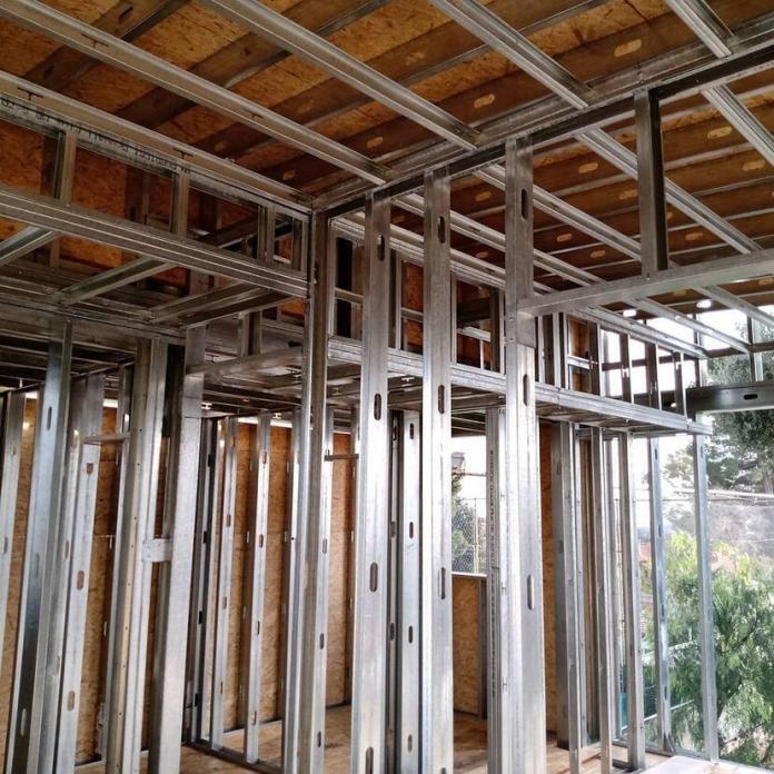
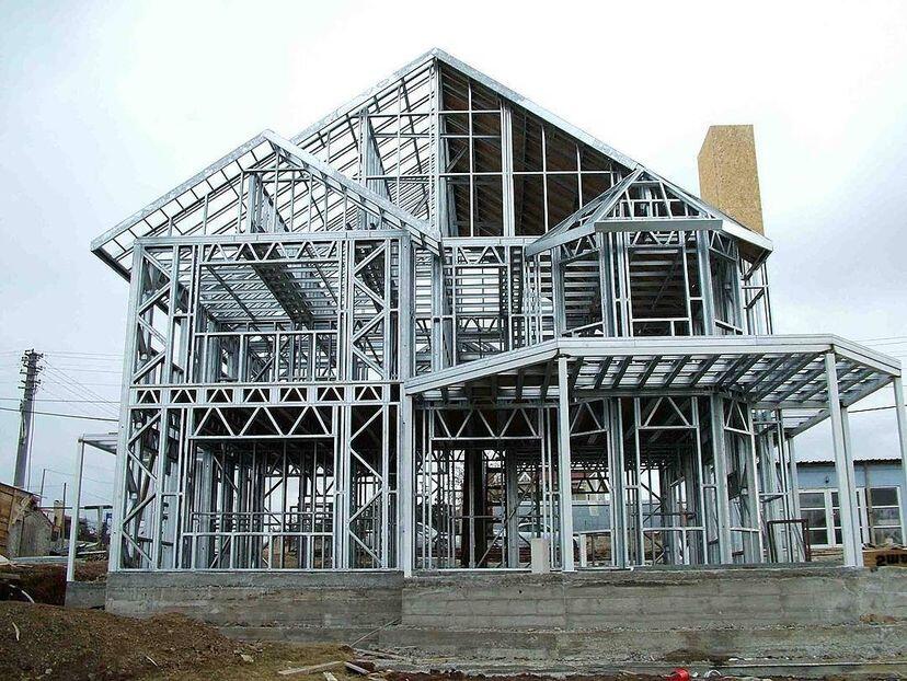
Axial compression loads from light gauge framed buildings must frequently be carried by light gauge steel members (cold-formed sections), such as the studs in a load-bearing wall. Similar to their hot-rolled counterparts, light gauge steel compression members’ failure is likely to be caused by buckling rather than cross-sectional yielding, yielding a member resistance that is much lower than the squash load of the section.
Since its buckling resistance must be calculated, the design process for such a member is in many ways comparable to that of hot-rolled steel columns. However, there are a number of ways in which the behaviour of light steel wall studs differs from that of hot-rolled columns, and these variations must be taken into account during the design process.
Contrary to columns, which function as separate parts inside a structural frame, load-bearing panels are created using light steel wall studs, plasterboard, and often some type of sheathing board. A certain amount of lateral constraint in the minor axis of the studs will be provided by the presence of the boards, which can be used to determine the buckling resistance. Any constraint must, however, be tested using studs of a representative slenderness range and a build-up of boards that is comparable to that used in actual practice.
While hot-rolled steel columns typically behave according to flexural buckling, many light steel sections can also buckle in a torsional-flexural manner. This form of failure will naturally control the member’s resistance if torsional-flexural buckling occurs at a lower magnitude of load than flexural buckling.
The elastic critical buckling load utilized for design is assumed to be the least significant of the elastic critical buckling loads for flexural buckling, torsional buckling, and torsional-flexural buckling. This is reflected in the Eurocode design guidelines.
Last but not least, light steel sections are prone to local and distortional buckling, both of which can negatively affect a member’s ability to withstand compression. When estimating the compression resistance, this should be taken into account by utilizing the effective cross-sectional area rather than the area of the gross cross-section.
Design Procedure According to the Eurocodes
Clause 6.2 of BS EN 1993-1-3 outlines the design processes for compression members made of light gauge steel. But because the design of hot-rolled columns is comparable, designers are directed to Clauses 6.3 of BS EN 1993-1-1 for the majority of the details, including the buckling curves.
When a light gauge steel member is subjected to axial compression, the design buckling resistance is given by:
Nb,Rd = χAefffy/γM1
Where;
χ is the reduction factor for flexural buckling
Aeff is the area of the effective cross-section
fy is the yield strength of the steel
γM1 is the partial factor of safety for buckling
The reduction factor χ is used to quantify the reduction in resistance below the squash load of the section due to buckling. It may be obtained from BS EN 1993-1-1 using the appropriate buckling curve and the value of slenderness λ corresponding to the critical mode of failure.
BS EN 1993-1-1 offers a choice of 5 buckling curves, but this is restricted to 3 curves for light gauge steel according to Clause 6.2.2 of BS EN 1993-1-3. The appropriate choice of curve for various types of cross-section is given in Table 6.3 of BS EN 1993-1-3.
The slenderness λ is given by:
λ = √(Aefffy/Ncr)
Ncr is the elastic critical buckling load, which for flexural buckling is equal to the Euler load and is given by:
Ncr = π2EI/Lcr2
where:
E is Young’s modulus for the material.
I is the appropriate second moment of area (for the gross cross-section).
Lcr is the effective length between points of restraint.
The reduction factor χ may be obtained directly from the buckling curves printed in BS EN 1993-1-1 or from the following equations:
Φ = 0.5 [1 + α(λ – 0.2) + λ2]
χ = 1/[Φ + √(Φ2 – λ2)]
α is the imperfection factor corresponding to the chosen buckling curve. Values of α are given in Table 6.1 of BS EN 1993-1-1.
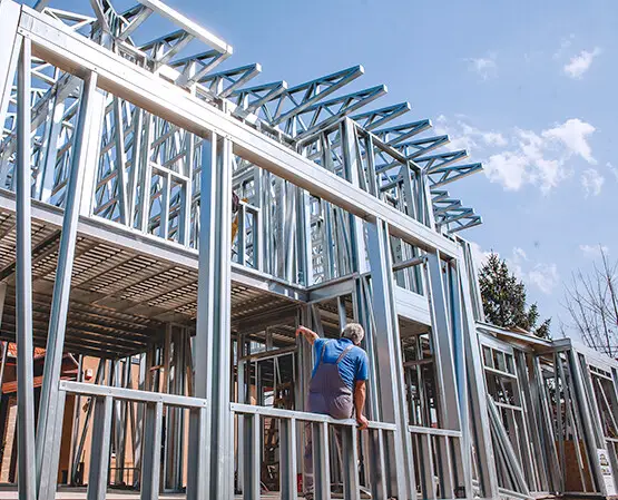
Design Example of Light Gauge Steel Columns
A light gauge steel building is to be constructed using cold-formed sections. Determine the buckling strength of a steel column in the wall stud constructed using a lipped channel section (200 x 65 x 2) which is restrained at the top at 3.5 m in the y-direction, and at 1.75m in the z-direction.
Length of member between restraints:
Ly = 3.50 m
Lz = 1.75 m
Effective lengths (assuming that the member is pin-ended):
Ly,cr = 3.00m
Lz,cr = 1.50m
Section depth h = 200 mm
Flange width b = 65 mm
Stiffener depth c =25 mm
Corner radius r =3 mm
Nominal thickness tnom = 2 mm
Core thickness t = 1.96 mm
Design strength fy = 350 N/mm2
Young’s modulus E = 210000 N/mm2
Partial safety factor γM1 = 1.00
Gross section properties
Area of gross cross-section A = 729 mm2
Second moment of area (major axis) Iy = 440.5 cm4
Second moment of area (minor axis) Iz = 44.26 cm4
Effective section properties
The effective area of the cross-section in compression: Aeff = 459.1 mm2 (This effective area has already been calculated by Heywood and Way, 2012).
Along the major axis;
Lcr,y = 3.5 m
Ncr = π2EI/Lcr2
Ncr = (π2 × 210000 × 4405000)/35002 = 745296.1266 N
λ = √(Aefffy/Ncr) = √(459.1 × 350)/745296.1266 = 0.464
Along the minor axis;
Lcr,z = 1.75 m
Ncr = π2EI/Lcr2
Ncr = (π2 × 210000 × 442600)/17502 = 299539.6737 N
λ = √(Aefffy/Ncr) = √(459.1 × 350)/299539.6737 = 0.732
The buckling curve b is appropriate for the y-y and z-z axis. The imperfection factor for buckling curve b, α = 0.34
Φ = 0.5 [1 + α(λ – 0.2) + λ2]
Φy = 0.5 [1 + 0.34 (0.464 – 0.2) + 0.4642] = 0.652
Φz = 0.5 [1 + 0.34 (0.732 – 0.2) + 0.7322] = 0.858
X = 1/(Φ + √(Φ2 – λ2))
Xy = 1/[0.652 + √(0.6522 – 0.4642)] = 0.900
Xz = 1/[0.858 + √(0.8582 – 0.7322)] = 0.765
Therefore;
Nb,Rd,y = (Xy Aeff.fy)/γm1 = (0.9 × 459.1 × 350) / (1.0) = 144616.5 N = 144.616 kN
Nb,Rd,z = (Xz Aeff.fy)/γm1 = (0.765 × 459.1 × 350) / (1.0) = 122924 N = 122.92 kN
In this case, the lesser holds for the flexural buckling resistance.
Hence Nb,Rd = 122.92 kN
Article reference:
Heywood M. and Way A. (2012): Design of light gauge steel elements. In Steel Designer’s Manual (Davison B. and Owens G. W. eds). Wiley-Blackwell,UK

