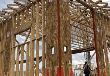
The use of timber as trussed rafters for roofs of buildings is a very popular alternative all over the world. Timber roof trusses are made up of a series of interconnected timber members that are arranged in a triangular pattern. This pattern allows the truss to distribute the weight of the roof evenly across its supports, making it a strong and efficient structural system.
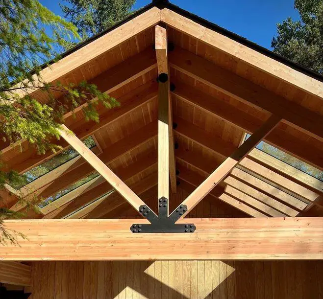
The aim of this article is to show the design example of a timber roof truss (trussed rafter). As a direct product of nature, timber has so many variable properties that are more complex than that of concrete, steel, bricks, or aluminium. Some of the characteristics which influence the structural behaviour of timber are;
- moisture content
- the direction of applied load (perpendicular or parallel to the grain)
- duration of loading
- strength grading of the timber
Steps in the Design of Timber Roof Trusses
Here’s a step-by-step overview of the design process for timber roof trusses:
1. Preliminary Design: In this step, the designer is to determine the roof span, pitch, and overall architectural design of the building. It is important to choose a truss configuration based on structural performance, aesthetic preferences, functional requirements, and available space.
2. Load Analysis: In this case, it is important to identify and analyze all relevant loads, including dead loads (roofing materials, insulation), live loads (snow, occupants), and potential wind or seismic loads. Calculate the total design load that the truss system must support.
3. Material Selection: Choose an appropriate timber species based on its mechanical properties, availability, and durability. It is important to consider factors such as bending strength, compression and tension properties, and resistance to decay.
4. Truss Geometry and Configuration: Based on the chosen truss configuration (e.g., king post, queen post, Howe truss), determine the angles, lengths, and dimensions of each timber member. It is important to ensure that the truss geometry is consistent with both structural and architectural requirements.
5. Member Sizing and Design: Calculate the axial forces, bending moments, and shear forces in each timber member using static equilibrium equations. Size each timber member to withstand the calculated forces while considering factors such as serviceability and durability.
6. Connection Design: Design secure and efficient connections between timber members using appropriate fasteners (nails, screws, bolts) and connectors (metal plates, brackets). Ensure that connections provide load transfer, prevent excessive movement, and account for potential wood shrinkage.
7. Lateral Stability and Bracing: Incorporate diagonal bracing or other lateral stability measures to prevent buckling or twisting of the truss members under lateral loads (wind or seismic forces).
8. Serviceability and Deflection Control: Assess the truss deflection under the designed loads to ensure that it meets acceptable serviceability criteria. Incorporate additional members or adjust member sizes if necessary to control deflection.
9. Fire Resistance and Protective Treatments: Consider fire resistance requirements by choosing fire-rated timber or applying fire-retardant treatments if needed. Apply appropriate protective coatings or treatments to enhance the truss’s durability and resistance to decay.
10. Detailed Drawings and Documentation: Create detailed construction drawings that specify the geometry, dimensions, connections, and material details of the truss members. Prepare design calculations and documentation that outline the design methodology, load assumptions, and member sizing.
Analysis of Timber Roof Trusses
Ideal trusses are theoretical structures in which the members meet at points called nodes. These nodes are idealized as hinges or pins, which means that they cannot transmit bending moments. Loads are applied to ideal trusses only at the nodes. This keeps the truss members free from shear and bending stresses and makes the analysis of the truss much simpler.
However, practical construction does not allow roof trusses to behave exactly as ideal trusses. The members of real-world trusses are not pinned at the nodes, and loads are often applied along the length of the chords. This means that practical trusses must resist bending moments and shear in addition to axial stress.
As a result, the classical methods of analyzing trusses are only valid for ideal trusses. These methods do not account for the bending moments and shear in practical trusses. As a result, the results of classical methods of analysis can be inaccurate for real-world trusses, even though they are usually employed.
Quickly in this post, I am going to carry out a very simple design example of timber roof truss using BS 5268. A lot of information regarding timber as a structural material can be obtained from specialist textbooks. It is worth knowing that the most current design code for timber structures is Eurocode 5.
Note:
BS 5268 is based on permissible stress design. When using permissible stress design, the margin of safety is introduced by considering structural behaviour under working/service load conditions and comparing the stresses thereby induced with permissible values. The permissible values are obtained by dividing the failure stresses by an appropriate factor of safety. The applied stresses are determined using elastic analysis techniques, i.e.
Stress induced by working loads ≤ (failure stress/factor of safety)
Since BS 5268 is a permissible stress design code, mathematical modelling of the behaviour of timber elements and structures is based on assumed elastic behaviour.
Solved Example
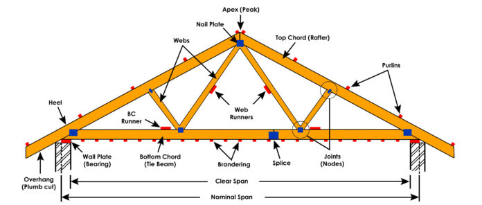
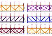
Let us design the roof truss of a building subjected to the following medium-term loads. The configuration of the roof truss is as shown above.
Data
Span of roof truss = 4.8m
Spacing of the truss = 2.0m
Nodal spacing of the trusses = 1.2m
Service class of roof truss: Service class 2
Load Analysis
(i) Dead Loads
On rafter (top chord)
Self-weight of long-span aluminium roofing sheet (0.55mm gauge thickness) = 0.019 kN/m2
Weight of purlin (assume 50mm x 50mm African Mahogany hardwood timber)
Density of African Mahogany = 530 kg/m3 = 0.013 kN/m = (0.013 × 2m)/(2m × 1.2m) = 0.0108 kN/m2
Self-weight of rafter (assume) = 0.05 kN/m2
Total = 0.0885 kN/m2
Weight on plan = 0.0885 × cos 17.35 = 0.08 kN/m2
On Ceiling Tie Member (bottom chord)
Weight of ceiling (10mm insulation fibre board) = 0.077 kN/m2
Weight of services = 0.1 kN/m2
Self weight of ceiling tie = 0.05 kN/m2
Total = 0.227 kN/m2
Therefore the nodal permanent load on rafter (Gk) = 0.08 kN/m2 × 2m × 1.2m = 0.192 kN
Therefore the nodal permanent load on ceiling tie (Gk) = 0.227 kN/m2 × 2m × 1.2m = 0.5448 kN
(ii) Live Load
Imposed load on top and bottom chord (qk) = 0.75 KN/m2 (treat as medium-term load on plan)
Therefore the nodal permanent load on rafter (Gk) = 0.75 kN/m2 × 2m × 1.2m = 1.8 kN
Analysis of the rafter (top chord)
Span Length = 1.257m
Load = (0.0885 + 0.75) × 2m = 1.667 kN/m
Results
Analysis of the structure for the loads gave the following results;
All load values are medium-term loads;
Medium-term load is defined in this case by:
Dead load + temporary imposed load
Top Chord Result
Axial force = 10.1 kN (Compression)
Bending Moment = 0.2 kNm
Length of member = 1.26 m
Design of the Top Chord
Let us try 38mm x 100mm timber
Strength class C18
Compression parallel to grain (σc,g,||) = 7.1 N/mm2
σc,adm,|| = σc,g,|| × k2 × k3 × k8 × k12
Bending parallel to grain (σm,g,||) = 5.8 N/mm2
σm,adm,|| = σm,g,|| × k2 × k3 × k6 × k7 × k8
k2 = wet exposure (does not apply in this case)
k3 = duration factor = 1.25 (medium-term loading)
k6 = shape factor = 1.0 (rectangular section)
k7 = Depth of section 72mm < h < 300mm
k7 = (300/h)0.11 = (300/100)0.11 = 1.128
k8 = Load sharing factor (does not apply since the spacing of the rafters exceed 610 mm).
Section Properties
Area = 3.8 × 103 mm2
Zxx = 63.3 × 103 mm3
Zyy = 24.1 × 103 mm3
Ixx = 3.17 × 106 mm4
Iyy = 0.457 × 106 mm4
rxx = 28.9 mm
ryy = 11 mm
Applied bending stress
σm,a,|| = M/Z = (0.2 × 10⁶)/(63.6 × 103) = 3.144 N/mm2
Axial compressive stress
σc,a,|| = P/A = (10.1 × 10³)/(3.8 × 103) = 2.657 N/mm2
Check for slenderness
Effective length (Le) = 1260 mm (assuming pin end connection)
λ = Le/r = 1260/28.9 = 43.598 < 52 Ok (clause 2.11.4)
Medium-term load
Compression parallel to grain (σc,g,||) = 7.1 N/mm2
Emin = 6000 N/mm2
k3 = 1.25 (Table 17)
σc,|| = 7.1 × 1.25 = 8.88 N/mm2
E/σc,|| = 6000/8.88 = 675.67
Slenderness λ = 43.598
We can obtain the value of k12 by interpolating from Table 22 of the code
We are interpolating for E/σc,|| = 675.67 and λ = 43.598
E/σc,|| 40 50
600 0.774 0.692
700 0.784 0.711
On interpolating (bivariate interpolation);
k12 = 0.7545
σc,adm,|| = σc,g,|| × k2 × k3 × k8 × k12
σc,adm,|| = 7.1 × 1.0× 1.25 × 1.0 × 0.7545 = 6.699 N/mm2
σm,adm,|| = σm,g,|| × k2 × k3 × k6 × k7 × k8
σm,adm,|| = 5.8 × 1.0× 1.25 × 1.0 × 1.128 × 1.0 = 8.178 N/mm2
Euler critical stress σe = π2Emin/λ2
σe = π2(6000)/(43.598)2 = 31.154 N/mm2
For combined bending and compression
σm,a,|| = 3.144 N/mm2
σc,a,|| = 2.657 N/mm2
σc,adm,|| = 6.699 N/mm2
σm,adm,|| = 8.178 N/mm2
σe = 31.154 N/mm2
[3.144/(6.699 × 0.9034)] + [2.657/6.699] = 0.919 < 1.0
Therefore, 38mm x 100mm GS C18 Timber is adequate for the rafter
Consider portion over nodes (at supports)
Bending moment = 0.28 kN.m
Axial load (taking the average at that joint) = (10.81 + 8.43)/2 = 9.62 kN
Applied bending stress
σm,a,|| = M/Z = (0.28 × 10⁶)/(63.6 × 103) = 4.40 N/mm2
Axial compressive stress
σc,a,|| = P/A = (9.62 × 10³)/(3.8 × 103) = 2.531 N/mm2
At node point, λ < 5.0, and the rafter is designed as a short column at this point;
σc,adm,|| = σc,g,|| × k2 × k3 × k8
σc,adm,|| = 7.1 × 1.0× 1.25 × 1.0 = 8.875 N/mm2
The interaction formula for this scenario is given below;
[σm,a,|| / σm,adm,||] + [σc,ma,|| / σc,adm,||] ≤ 1.0
[4.40 / 8.178] + [2.531 / 8.875] = 0.8232 < 1.0
This shows that the section is satisfactory for rafter.
Analysis of Tie Element
Span Length = 1.2m
Load = (0.227 + 0.75) × 2m = 1.954 kN/m
Results
Axial force = 9.74 kN (tension)
Bending Moment = 0.22 kNm
Length of member = 1.2m
Design of the Bottom Chord (ceiling tie)
Let us still try 38mm x 100mm timber
Strength class C18
Tension parallel to grain (σt,g,||) = 3.5 N/mm2
σt,adm,|| = σt,g,|| × k2 × k3 × k8 × k14
(width of section) k14 = (300/h)0.11 = (300/100)0.11 = 1.128
σt,adm,|| = 3.5 × 1.0× 1.25× 1.0 × 1.128 = 4.935 N/mm2
Bending parallel to grain (σm,g,||) = 5.8 N/mm2
σm,adm,|| = 5.8 × 1.0× 1.25 × 1.0 × 1.128 × 1.0 = 8.178 N/mm2
Applied bending stress
σm,a,|| = M/Z = (0.22 × 10⁶)/(63.6 × 103) = 3.459 N/mm2
Axial tensile stress
σc,a,|| = P/Effective Area = (9.74 × 10³)/(3.8 × 103) = 2.563 N/mm2
Note: When the ceiling tie is connected to rafter by the means of a bolt, the projected area of the bolt hole must be subtracted from the gross area of the section.
Combined tension and bending
[σm,a,|| / σm,adm,||] + [σt,ma,|| / σt,adm,||] ≤ 1.0
[3.459 / 8.178] + [2.563 / 4.935] = 0.9422 < 1.0
This is ok.
Consider portion over nodes (at supports)
Bending moment = 0.3 kN.m
Axial load (taking the average at that joint) = (9.5 + 9.74)/2 = 9.62 kN
Applied bending stress
σm,a,|| = M/Z = (0.3 × 10⁶)/(63.6 × 103) = 4.7169 N/mm2
Axial tensile stress
σc,a,|| = P/Effective Area = (9.62 × 10³)/(3.8 × 103) = 2.531 N/mm2
Combined tension and bending
[σm,a,|| / σm,adm,||] + [σt,ma,|| / σt,adm,||] ≤ 1.0
[4.7169/ 8.178] + [2.531 / 4.935] = 1.089
In this case, the tie element may be increased to 38mm x 175mm or the grade of the timber could be changed to accommodate the combined flexural and axial stress in the member.
Check for deflection
Deflection of trussed rafter under full load = 6.095 mm (calculated on Staad)
Permissible deflection = 14 mm
Deflection is ok.
That is it for now. Thank you so much for visiting Structville today and God bless you. Remember to share with your folks.



Wow ranks, u r doing a tremendous work here I must confess. Your post has been colossal source of my bank of knowledge. God will reward u greatly. Thanks fr d post.
Great knowledge acquired. Thanks.
Nice Content Thanks for sharing .. BIM Solutions in India
BIM Project Management in India
BIM Implementation in India
Documentation Services in India
ANIMATION SERVICES in India
You’ve got some interesting points in this article. I would have never considered any of these if I didn’t come across this. Thanks!. navigate here
very interesting keep posting. ux design companies
Great stuff. This is educative and the basic calculation enhances insight to structural and
lysis.
That’s very informative. Thank you!
Commendable design over here. Thanks for this it will help even the generation to come
Thanks for helping me understand that Eurocode 5 is the most current design code used for timber roof truss suppliers. I wonder if that is the same for other locations or countries, since it might depend on their structure and environment as well. The best thing to do is to rely on professionals who have been in the industry for a long time to be able to get the right materials and the proper construction process as well.