Utilizing void formers of some sort to create a voided slab is one of the most popular ways of reducing the weight of a solid slab. In the design of bridges, the deck serves as the primary component for distributing the traffic load to the supports. The deck slab may be solid or have longitudinal and transverse girders to distribute the load to the piers or abutment.
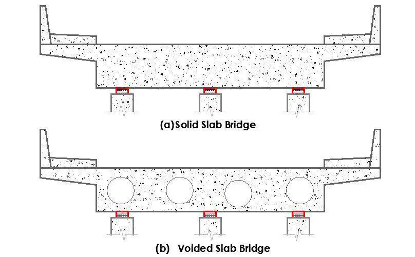
For the same span, solid slab type bridges require more steel and concrete than girder bridges do. The major load-bearing components of slab type superstructure bridges are the slabs themselves. Through the solid slabs, the loads are directly transferred to the substructure. Solid slab decks comprises of a solid section, without beams or voids (See Figure 1a). This type of deck is commonly used in the construction of short span bridges and culverts.
The dead load of a solid slab increases excessively for bridge spans longer than 10 metres, so to lighten the structure, voids with rectangular or circular cross sections are added close to the neutral axis (See Figure 1b). As a result, the use of voids inside the deck slab produces a favourable outcome by reducing the weight of the slab.
When the voids are less than 60% of the overall structural depth, their effect on stiffness is minimal and the deck behaves more or less like a plate. In order to assure continuity in the transverse direction, voided slab decks are often constructed using cast in situ concrete with permanent void formers or precast prestressed concrete box beams post tensioned transversely.
In effect, slabs that have voids within them are known as voided slabs. The voids, which are typically cylindrical, are made by embedding hollow, thin-walled steel parts into the slab. The slab’s voids contribute to the reduction of the structure’s self-weight. Voided slabs’ primary purpose is to reduce the volume of the concrete and, as a result, the slab’s self-weight.
If properly designed, it can lower the self-weight of the slab by up to 35% for the same section and span when compared to a solid slab. If the void diameters are less than 60% of the slab depth, voided slabs can be modelled and designed using the same methodology as solid slabs.
Construction Methodology of Voided Slabs
The two main techniques for constructing voided slab systems are the filigree method, in which some components are precast at a workshop or concrete yard, and the on-site method, in which the entire system is cast in situ. Both techniques require the use of void formers, reinforcements/strands, and concrete.
Void forming is an essential part of voided slab construction. Plastic voids can be used in both techniques of voided slab construction. These voids are usually formed from recycled plastic, which is spherical and hollow. The presence of voids makes the slab lighter than conventional solid concrete slabs.
However, the commonest form is circular polystyrene void formers. Although polystyrene appears to be impermeable, it is only the much more expensive closed cell form which is so. The voids should therefore be provided with drainage holes at their lower ends. It is also important to ensure that the voids and reinforcement are held firmly in position in the formwork during construction. This avoids problems that have occurred with the voids floating or with the links moving to touch the void formers, giving no cover.
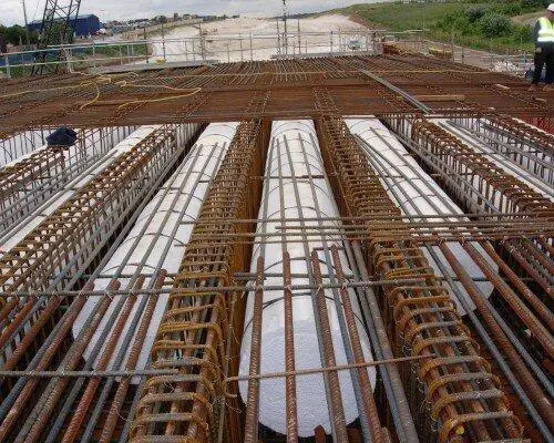
The steel reinforcement or tendons (for post-tensioned construction) is an additional important component. The slab is reinforced with steel to prevent flexural failure, and the voids are held in place in the middle of the slab by a cage of thin steel. The concrete that encloses the voids is the third element. The strength of the slab is ultimately determined by the concrete.
Advantages of Voided Slab
- Reduction in dead weight up to 35% allows cost reduction in substructure i.e. footing and Piers. The structural engineer can lighten the floor by more efficiently using the concrete.
- Reduced concrete usage- The use of 1 kg recycled plastic void former can replace 100 kg of concrete thereby, leading to environmentally green and sustainable construction with reduced energy and carbon emissions.
- It allows longer spans between columns without increasing the thickness of the slab by large. Voided slabs can take advantage of post-tensioned reinforcement benefits to provide a thin slab with a greater span.
- The elimination of downstand beams allows the quicker and cheaper erection of shuttering and services. Flat-plate construction eliminates beams and drops, resulting in reduced floor-to-floor heights.
- Some voided-slab systems can reduce construction time, especially precast systems or those placed on flat-plate forming systems.
- Voided slabs are beneficial in seismic design since the reduced dead weight of floors results in lower seismic forces applied to structures.
- This reduced weight of building floors also permits engineers to reduce columns, walls, and foundations by as much as 40%, although concrete can’t be removed from all locations in a floor slab; voids are omitted near columns to maintain slab punching-shear capacity.
Design of Voided Slab Bridge Decks
The bridge can be analysed similarly to a solid slab as long as the void diameters are less than or equal to 60% of the slab thickness and nominal transverse steel is given in the flanges. In other words, the slab can be designed without taking into account either the decreased transverse shear stiffness or the local flange bending. EN 1992-2, in contrast to the earlier British regulation, does not provide particular guidelines on voided slabs. The British Standards Institution’s accompanying “PD” does, however, contain some information.

The voided slab section is designed longitudinally in both flexure and shear, making appropriate allowance for the voids. Links must be provided, and they are designed as done for flanged beams, bearing the beam’s thinnest web thickness in mind. Particularly if isolated piers are utilised, the shear loads are likely to increase excessively close to the supports. To solve the issue, the void can be easily closed off, leaving a solid part in these critical regions.
Larger diameter voids or square voids forming a cellular deck can be employed if more weight reduction is needed. The analysis must therefore take these into account. The section is treated as a monolithic beam for the purposes of calculating the longitudinal stiffness to be employed for a cellular deck. Under uniform and non-uniform bending, such a structure responds differently in the transverse direction. The top and bottom flanges rotate about their individual neutral axes in the latter case while acting compositely in the former.
This indicates that with uniform bending as opposed to non-uniform bending, the accurate flexural inertia can be an order of magnitude higher. However, the behaviour can be modelled using a shear deformable grillage in a standard grillage model. Utilizing the composite flexural characteristics, an equivalent shear stiffness is calculated to represent the additional distortion caused by non-uniform bending.


The reinforcement should be designed once the moments and forces in the cellular structure have been determined. Local moments in the flanges must be taken into account in addition to the longitudinal and transverse moments in the entire section. This results both from the transverse shear and the wheel loads placed on the deck slab. This shear has to be transmitted across the voids by flexure in the flanges, that is by the section acting like a vierendeel frame.
To improve the structural response and to avoid undesired tensile forces in the concrete, post-tensioned steel tendons are embedded into the concrete at the final stages of construction. The common layout of the tendons is parabolic, with negative eccentricities in the mid-span and positive in the pier zones.
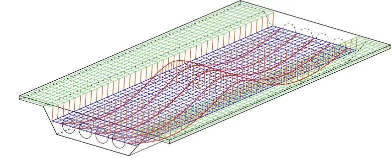
Grillage Analysis for Voided Slab Decks
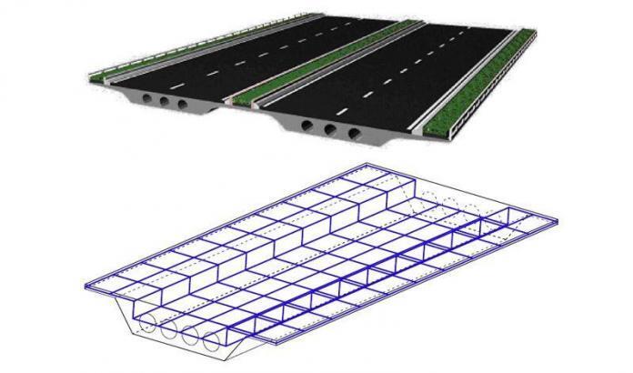
Despite the obvious benefits of voided slab decks, the analysis of the structural model is made more difficult by the voided slab form. While a voided slab has a varying amount of material depending on the direction, a solid slab with a consistent thickness has the same bending stiffness in all directions. As a result of this, defining grillages in the longitudinal and transversal deck directions is a highly popular option, where the grillage’s longitudinal beams are situated in the areas between voids, as shown in Figure 7.
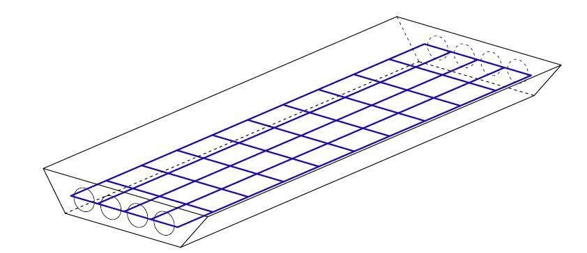
However, the stiffness attributed to each element in the grillage must be adjusted since in this discretization one-dimensional structural elements are used to describe the performance of a two-dimensional plate. The planar grillage analogy is said to be inaccurate when cantilevers are present, therefore a three-dimensional grillage is necessary, like the one in Figure 8, where the layer discretizing the voided slab and the layer modelling the cantilevers are joined together using stiff components.
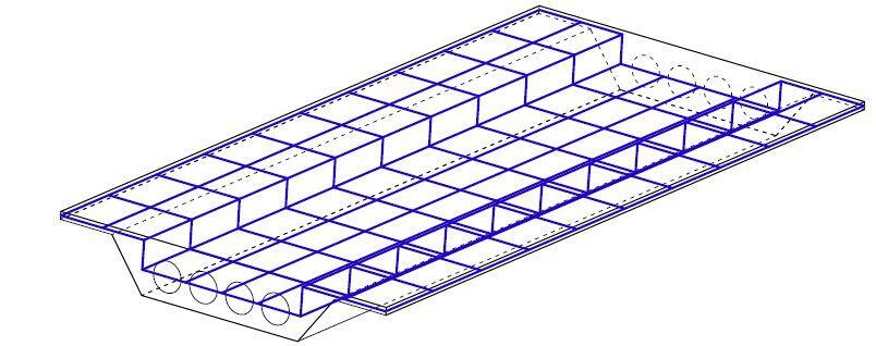
The grillage model, however, is an approximation of the deck’s actual behaviour and does not adequately capture the coupling of the slab in torsion or the local effects. Therefore, it is beneficial to create structural models, such as the orthotropic plate technique, that more accurately depict the deck’s resistance scheme.
Reference(s)
Díaz J., Hernández S., Fontán A., Romera L. (2010): A computer code for finite element analysis and design of post-tensioned voided slab bridge decks with orthotropic behaviour. Advances in Engineering Software 41 (2010) 987–999 doi:10.1016/j.advengsoft.2010.04.005

