Tall masts are used in a variety of applications such as telecommunication, radio/television broadcasting, supporting lighting fixtures on the highway, raising flags, etc. Due to their height above the ground, these structures are usually subjected to wind action, and this makes the knowledge of their behavior under the effect of wind very important.
The dynamic behavior of telecommunication masts under the effect of wind is studied under ‘flow-induced vibration of structures’. This term is used to denote the phenomena associated with the response of a structure immersed in or conveying fluid flow. It covers those cases in which an interaction develops between fluid dynamic forces and the inertia, damping, or elastic forces in the structure. The study of these phenomena draws on three disciplines which are, structural mechanics, mechanical vibration, and fluid dynamics (Ahmad, 2009).
Read Also …
Effects of wind on different configurations of telecommunication mast
Design of Roof Purlins
This article investigates the natural frequency of vibration of X-braced and V-braced (Chevron bracing) telecommunication masts. To advance the study, the wind-induced vibration can be investigated using Staad Pro software (finite element analysis) in order to determine the critical wind speed that will potentially lead to resonance in the structure under the effect of wind. Resonance occurs when one of the natural frequencies of the structure coincides with the frequency of the vortices shedding around the mast due to the effect of wind.
Methodology
To carry out this study, two models of telecommunication masts were considered;
MODEL 1
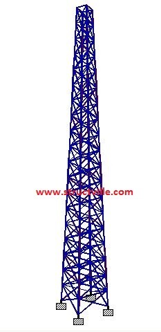
Type: X-Bracing
Height: 30 m
Width at the base: 3m x 3m
Width at the top: 1m x 1m
Section of the legs: UA 100 x 100 x 8
Section of the horizontal bracings and diagonals: UA 50 x 50 x 6
Solidity ratio: 20.6%
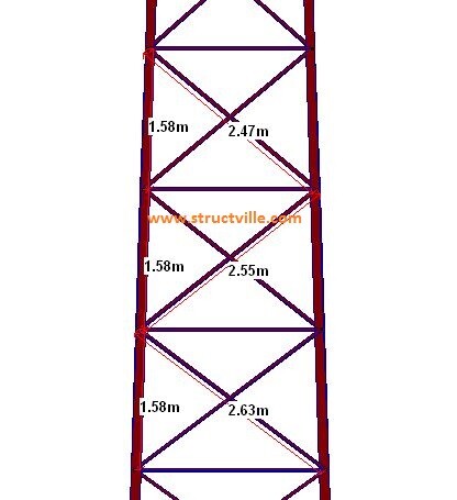
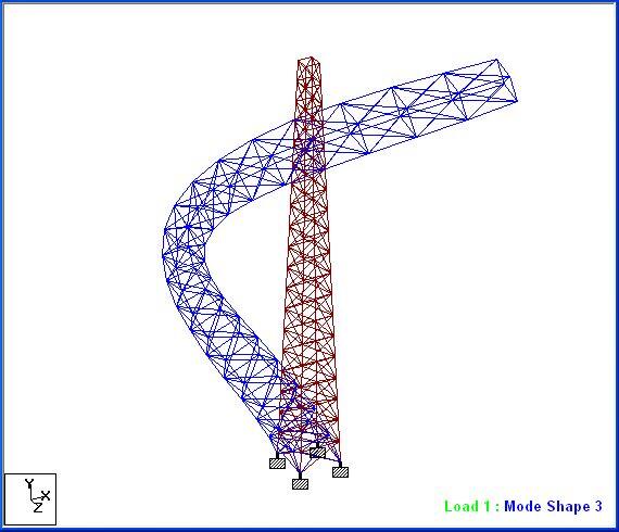
The first four fundamental natural frequencies of the structure were obtained as follows;
| Mode | Frequency (Hz) | Period (Sec) | MPF-X (%) | MPF-Y (%) | MPF-Z (%) |
| 1 | 2.637 | 0.379 | 32.303 | 0.000 | 24.153 |
| 2 | 2.637 | 0.379 | 24.153 | 0.000 | 32.303 |
| 3 | 11.568 | 0.086 | 13.073 | 0.000 | 9.760 |
| 4 | 11.568 | 0.086 | 9.760 | 0.000 | 13.073 |
N/B: MPF – Mass participation factor

Have some time?
Take a quiz on THEORY OF STRUCTURES
MODEL 2
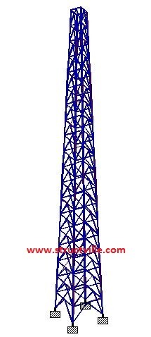
Type: V-Bracing (Chevron Bracing)
Height: 30 m
Width at the base: 3m x 3m
Width at the top: 1m x 1m
Section of the legs: UA 100 x 100 x 8
Section of the horizontal bracings and diagonals: UA 50 x 50 x 6
Solidity ratio: 19.51 %
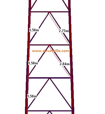
The first four fundamental natural frequency of the structure were obtained as follows;
| Mode | Frequency (Hz) | Period (Sec) | MPF-X (%) | MPF-Y (%) | MPF-Z (%) |
| 1 | 2.775 | 0.360 | 26.153 | 0.000 | 30.132 |
| 2 | 2.775 | 0.360 | 30.132 | 0.000 | 26.153 |
| 3 | 11.390 | 0.088 | 9.021 | 0.000 | 14.375 |
| 4 | 11.390 | 0.088 | 14.375 | 0.000 | 9.021 |
N/B: MPF – Mass participation factor
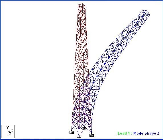
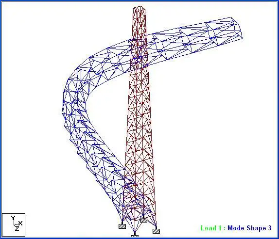
Time history analysis can be used to evaluate the response of the mast to periodic vortex shedding excitations. It is a step-by-step analysis that involves solving the dynamic equilibrium equations given by;
Kx(t) + Cẋ(t) + Ṁẍ(t) = r(t) (1)
Where,
K is the stiffness matrix
C is the proportional damping matrix
Ṁ is the diagonal mass matrix
x is the relative displacements with respect to the ground
ẋ is the relative velocities with respect to the ground
ẍ is the relative accelerations with respect to the ground
r is the vector of the applied load.
t is time
The load r(t) applied in a given Time-History analysis may be an arbitrary function of space and time. It can be written as a finite sum of spatial load vectors multiplied by time function. The frequency of vortex shedding (fv) is related to the Strouhal number (S) and the relationship is given by;
S = fvW/U —— (2)
Where W is the average outside width of the mast (m). The value of ݂fv is calculated for different values of velocities. The velocity values chosen should result in Reynolds number (Re) values that still fall in ranges of constant Strouhal number S = 0.21 for low speeds and 300 < ܴ݁Re < 2 x 10⁶ or ܵS = 0.27 for high speeds and ܴ݁Re > 3.5 x 10⁶.
From equation (2) we can deduce that;
fv = SU/W ——- (2a)
For resonance to occur, note that fv = fs (where fs is the natural frequency of the structure)
Note that we can calculate the range of velocities based on Reynolds’s number. The Reynolds numbers that can be used for this purpose are 300, 2 x 10⁶ and 3.5 x 10⁶.
Re = UW/vair (3)
Where vair is the kinematic viscosity of flowing air (ν = 1.51 x 10⁻⁵ m2/s at standard atmospheric pressure and 20oC).
However, it should be noted that a latticed tower has a complex aerodynamic shape to the wind such that consistent vortex shedding to cause complete oscillation of the structure over a prolonged period is almost impossible. This is because the vortex shed from the different trussed members can rarely have a uniform frequency, thereby reducing the possibility of vortex-induced vibration. However, for towers with circular or tubular cross-section over the whole or part of its body, vortex-induced vibration is a possibility.








really this subject!
really good