Since ancient times, people all over the world have practised the art of strengthening earthen structures with brushwood, bamboo, straw, and other materials of a similar nature. The additional strength added by such reinforcements gave birth to mechanically stabilised earth (MSE) walls and structures.
In the year 1963, a French architect and engineer named Henri Vidal was successful in obtaining a patent for a general configuration of applying the aforementioned principle to the construction of embankments. It was adopted for retaining walls, bridge abutments, dams, foundations, and several other applications on a global scale.
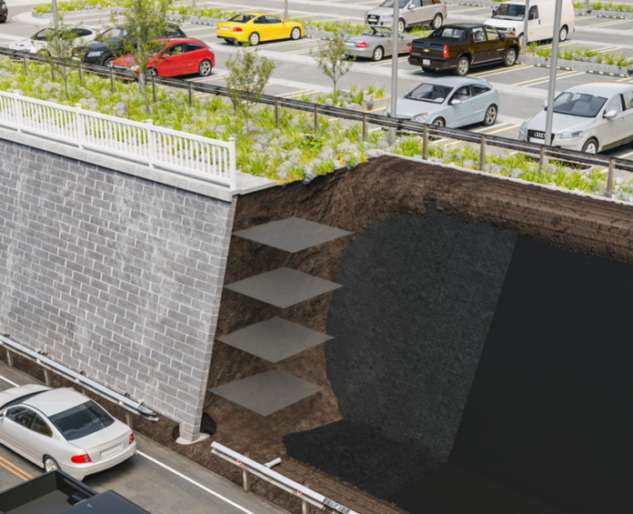
The following three fundamental elements make up the patented general configuration, as shown in Figure 1.

- The earthfill (often chosen granular materials passing US sieve no. 200 with less than 15%).
- Soil reinforcement. Currently, this takes the shape of metal strips, geotextiles, or wire grids that are attached to the facing unit and extend enough into the earth backfill. To reduce the length of the anchorage length required, special end anchorages can also be offered.
- The facing unit (this is usually made of metal or concrete blocks made to maintain an aesthetic appearance of the structure and prevent soil erosion).
The Mechanism of MSE Wall
The friction generated at the soil reinforcement interfaces to stop the relative motion of the soil and reinforcement is an important component of the MSE mechanism. The reinforcements provide an apparent cohesion proportionate to the density and tensile resistance of the reinforcement and limit the lateral deformation of the reinforced earth mass.
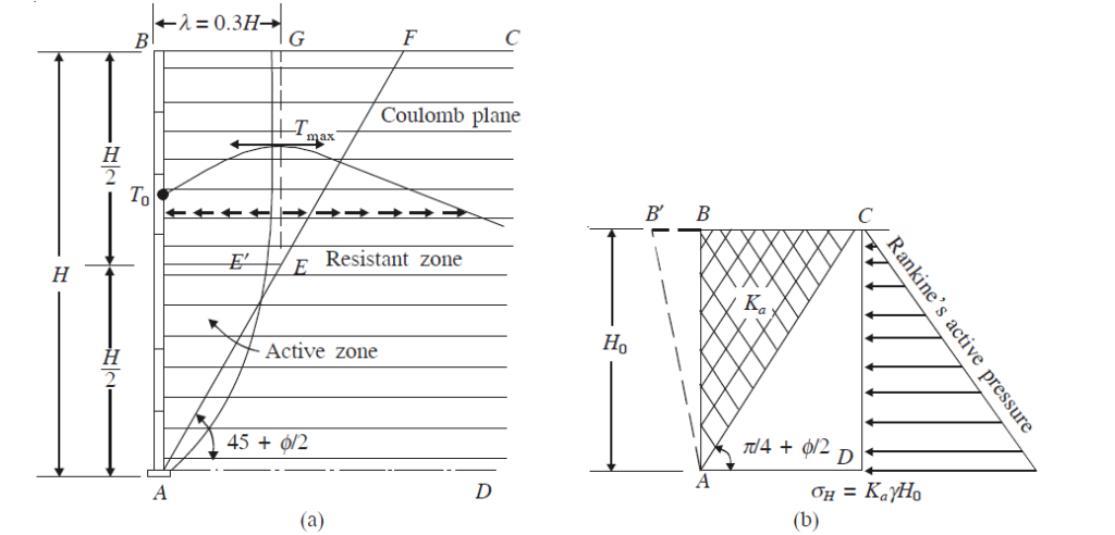
Depending on the type of structure and the loading conditions, the greatest tensile force in the reinforcement occurs at a distance from the mechanically stabilised earth wall. The reinforced earth is separated into the two zones shown below along this line of maximal tensile force;
- An active zone behind the facing where the shear forces are directed outward giving rise to an increase of tensile forces in the reinforcements.
- A resistant zone, where the shear stresses are mobilized to prevent the sliding of the reinforcement which is directed towards the free end of the reinforcement inside the embankment.

Full-scale experiments and observations show that the behaviour of reinforced earth walls is quite different from that of classical retaining walls. The locus of the maximum tensile force in the reinforcement has been found to be different from Coulomb’s failure plane.
The remarkable features of mechanically stabilized earth (MSE) are the following:
- Strength – It can resist significant earth pressure and seismic force.
- Flexibility – They are flexible gravity structures. It adapts to substandard foundation soils and large settlements. (This is one of its main advantages over rigid walls.)
- Construction – It can be easily constructed by untrained labour.
- Low costs – Costs are low.
- Aesthetic factors – It has good appearance as the facing can be made of attractive designs.
Design of Mechanically Stabilised Earth Walls
Mechanically stabilised earth walls should be designed against the following types of failures:
- Tension failure of the reinforcement in the earth (internal stability)
- Bearing capacity failure of the base (external stability)
- Sliding of the whole block ABCD along the base (external stability)
- Overturning and tilting under the horizontal earth pressure acting on the mass.
Usually, the effect of surcharge in concentrated load is assumed to be distributed using the 2 vertical to 1 horizontal distribution as in Figure 3.
The following two types of design methods are used for determining the tension in reinforcements:
- The working stress method
- The failure plane method (limit state method).
In the working stress method, we assume the surface of maximum tension in the reinforcement based on experimental values and work out the necessary anchorage length required for the soil reinforcement. It is used as a general case to deal with all types of reinforced earth walls.
In the failure plane method, we consider the equilibrium of several wedges along a potential failure plane and estimate the tension to be developed in the steel reinforcement. We then design for maximum tension. As the working stress method is the more popular and general method, we will discuss only this method in this chapter. The conservative Coulomb’s failure surface is also assumed as the surface of failure plane.
Reinforcement Design of Mechanically Stabilised Earth Wall
The design procedure is as follows for a retaining wall without any surcharge:
Step 1: Adopt vertical and horizontal spacing of the reinforcement to be used. It may range from 0.2 to 1 m vertically and 0.7 to 1m horizontally.
Step 2: Assume the locus of maximum stress in the soil reinforcements. Different authorities have suggested different locus as shown in Fig. 26.2. The most commonly used is the conservative Coulomb’s failure plane.
Step 3: Determine the magnitude of horizontal pressure at various depths due to earth pressure as well as due to any superload on the embankment. Usually, the active earth pressure distribution is assumed and the pressure due to superload may be approximately evaluated by using 2 vertical to 1 horizontal distribution.
Step 4: Take each reinforcement strip and determine the maximum tension that will be developed in it. Let it be Ti. Thus, take the reinforcement strip at depth z from the top. The friction f developed will depend on the pressure on the strip and the coefficient of friction f = γztanδ.
If b is the width of the strip assuming that friction acts on both faces, the anchorage length La required to anchor Ti will be as follows:
La = Ti/2bf = Ti/(2bγztanδ)
where;
Ti = tension in soil reinforcement
b = breadth of the reinforcement
γz = pressure at depth z
f = friction developed between soil and reinforcement = tan δ
Ti = (γgKA) × (area of influence of reinforcing strip)
For each strip, find La, the anchorage length required to develop the corresponding anchorage.
(Note: In the field, for easiness of fabrication and installation, all the strips are made of the same length equal to the required maximum anchorage length.)
Soil Reinforcement Selection
It is important to choose the MSE reinforcement carefully. Low-creep materials are necessary for rigid structures like retaining walls. Materials with some creep may be advantageous for embankments that may consolidate over time. Nonmetallic reinforcements are weaker than metallic reinforcements like galvanized steel and stainless steel (used to reduce corrosion).
Corrosion resistance is a benefit of plastics. Plastics come in both fabric and nonfabric forms. Fabrics are created by weaving or knitting textiles. Grids and strips make up non-fabrics; the latter is occasionally strengthened with glass fibre. In any case, these reinforcements should be chosen only after a thorough examination of their strength, creep, and durability properties. Based on the outcomes of laboratory tests provided by the manufacturer or by accredited laboratories, they should base their decision.
Reference:
Varghese P. C. (2012): Foundation Engineering. PHI Learning Private Limited, New Delhi

