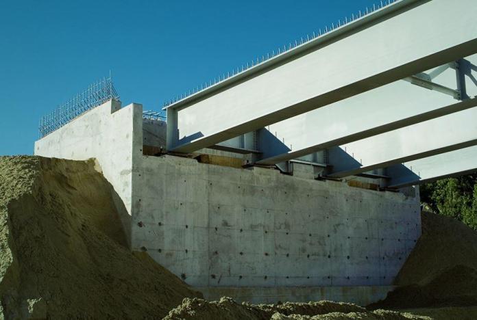
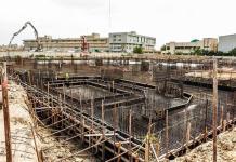
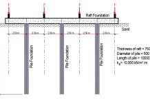
End supports and intermediate supports are two separate categories of bridge substructures. The intermediate supports of multi-span bridges are referred to as “piers,” while the end supports are typically referred to as “abutments.” Abutments and piers of bridges are typically built from in-situ concrete. As a part of the bridge, the abutment connects the bridge to the approach roadway, gives the bridge superstructure vertical support at the bridge ends, and retains the roadway earth materials from the bridge spans.
Typically, bridges are built as part of a railway or road highway project. Although the cost of the bridges may only make up a small portion of the overall contract, the construction of the bridge substructures can significantly affect the overall contract schedule because it invariably falls on the critical path for construction and typically takes place concurrently with earthmoving and drainage operations. More than half of the costs of a bridge is frequently spent on the foundation that supports the bridge deck.
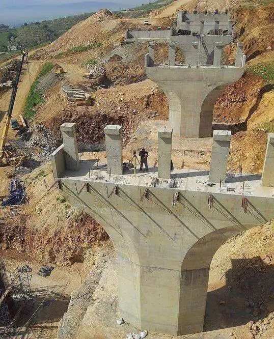
Types of Abutment
The selection of appropriate abutments for a bridge should be made at the same stage as the choice of the deck superstructure. There are many types of abutment in use all over the world. Abutments can be categorised into the following;
- Solid or full height abutments
- Skeletal or open abutments
- Mass concrete bankseats
- Integral abutments
- Semi-integral abutments
- Reinforced earth abutments
The criteria for the bridge’s design must be taken into account while choosing an abutment type. Bridge geometry, needs for the road and riverbanks, geotechnical conditions, right-of-way limits, requirements for the architect, and other factors might be among them. The ability to compare the benefits and drawbacks of the various types of abutments will help the bridge designer make the best choice for the bridge construction from the outset of the design process.
Cantilever Abutment Walls
For bridges without integral abutments, the T-section reinforced concrete cantilevered wall has remained the most popular method of construction for the solid wall type of bridge abutment. To meet various needs, the core concept has been modified in a number of ways.
For right bridge decks with spans under 12 metres, sloping abutments for aesthetic or clearance reasons, and counterfort walls for heights of 10 metres and above, propped cantilever walls are frequently employed. The overall height of a solid wall abutment is automatically in the range of 7-9 m because the minimum headroom for new highway bridges is often higher than 5.1 m. Because mass concrete retaining walls are not cost effective at this height, reinforced cantilever abutment walls are now used extensively.
The simplicity of this form of construction and the similarity with cantilever retaining walls also accounts for its economic success and popularity.
Free Cantilever Abutment Walls
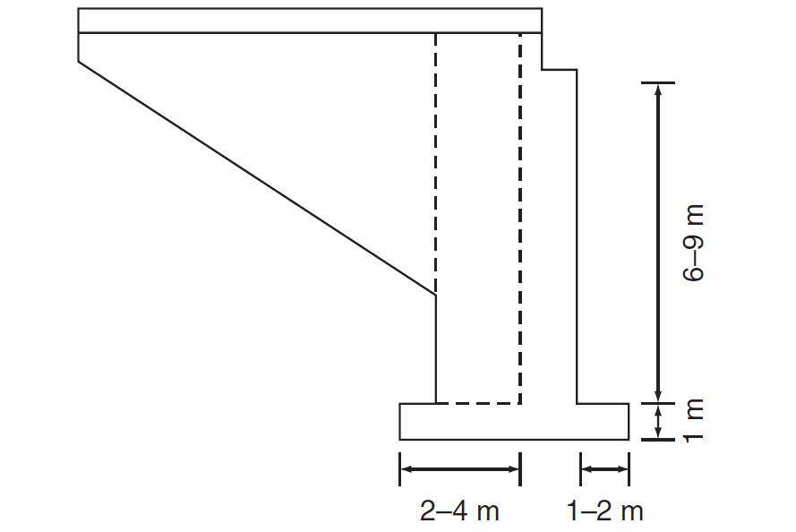
For heights of 6 to 9 metres, plane cantilever abutment walls are the most popular type of construction, and despite their size, the main concrete wall is frequently poured in a single lift. The wall stem typically measures between 0.9 and 1.2 metres in width, making it possible for someone to enter the reinforcing cage while it is being constructed. The base will often be 0.4–0.6 times wider than it is tall, and the toe may extend 1.0–2.0 m in front of the wall.
The soil foundation conditions and available sliding resistance will, nevertheless, affect the base’s physical proportions and dimensions. Figure 6 shows a typical illustration of a cantilever abutment wall with horizontally cantilevered wing walls.
Active earth pressure conditions are typically used for overturning, sliding, and bearing pressure calculations where an abutment wall can rotate around its base or slide horizontally. The lateral earth pressure behind the abutment wall has typically been assumed to be in the at-rest state for walls that are tightly supported, such as on a mix of vertical and raking piles.
To account for high pressures during the backfill material’s compaction, the wall stem design is typically based on at-rest conditions in all circumstances. On the assumption that the abutment wall solely functions as a vertical cantilever, the design forces are frequently estimated using a metre-wide strip. There is a compelling justification for taking the structure’s three-dimensional behaviour into account if wing walls are joined to the back of the abutment.
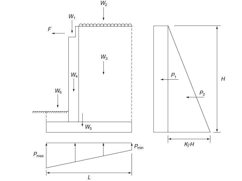
The main abutment wall’s need for vertical reinforcement can be decreased to a nominal proportion of the cross-sectional area when the weight of the wing wall and significant corner splays are combined. Figure 4 depicts an idealised system of forces acting vertically and horizontally on a straightforward cantilever wall. It is foolish to rely on passive pressure at the front of the wall since excavations for highway services may be introduced along the foundation’s toe, entirely removing the soil.
Counterfort Abutment Walls
For heights more than 10 m, where the percentage reinforcement in a free cantilever becomes quite large, counterfort abutment walls become economically viable. To increase flexural stiffness and resist the lateral earth pressures created by the depth of backfill material, triangular counterforts are added to the back of the abutment wall slab.
The reinforcement and formwork surrounding the counterforts make the building more challenging, and it is more difficult to physically compact the backfill. The counterforts are vertical cantilevers that are separated at about half the height of the wall. Although the wall slab naturally spans the shorter horizontal distance between the counterforts, it can be treated as a slab clamped on three sides, allowing the wall thickness to be decreased. The heel of the base slab also spans between the counterforts.
The primary tensile reinforcement’s anchorage length at the back of the counterforts, however, is a limiting element, therefore there is typically minimal room for thickness reduction.
Propped Cantilever Abutments
Bridge decks up to a 12 m span have minimal longitudinal movement, making it possible to employ the deck as a strut for square or skew-free bridges. Although the abutments can be planned as a supported cantilever, at-rest earth forces are typically assumed for the design of reinforcement at the back of the wall and footing, as well as both stability and bearing pressure calculations, due to the inflexible character of the structure.
Since complete fixity of the foundation is improbable, it is common practise to estimate the front face reinforcement in an abutment by assuming that the wall is pinned at both the deck and base levels. The rear curtain walls at the top of the abutments are made to withstand the propping force and are typically used to separate the deck from the top of the abutments.
To prevent rotation and horizontal displacement of the abutments, it is frequently important to specify that the initial backfilling before the deck is built should be kept to a maximum of 50% of the abutment height. The deck’s completion is then postponed until the backfill behind the abutment walls is finished.
Open Abutments
The type of end supports required to extend a bridge’s central span and produce neighbouring “open side spans” are known as “open abutments,” and they are frequently used in construction terminology. In this case, abutments come in two different basic varieties; a subterranean reinforced concrete or piled skeleton or “spill-through” abutment formed at or below previously existing ground level beneath an embankment slope, or a mass concrete bankseat located at the top of the slope and includes a side span.
A three-span deck with intermediate piers and end abutment supports is an alternative to a single-span deck with solid cantilever abutments. Therefore, the prices of two intermediate piers, two end abutments, and two additional deck spans may be contrasted with the costs of two massive cantilever abutments, related wing walls, and chosen granular backfill. The choice of a three-span open structure must also take into account aesthetics, sightlines, flood relief, and pedestrian safety.
Bankseats
When the foundation level is near to the existing ground level, simple mass concrete or minimally reinforced sections may be used for abutment supports at the top of cuttings. This kind of structure is typically “stepped out” in sections to lessen foundation strain and keep the force that results on the bankseat inside the middle part of its base. To limit the immediate region of backfill behind the wall, little wing walls that hang easily from the back of the bankseat can be used.
Bankseats can also be utilised on embankments, where they can either be supported directly on pile foundations or allowed to settle with the fill. In the latter scenario, pile downdrag due to embankment settlement might lower the payload of the pile group unless isolating sleeves are utilised. Driving raking piles for a bankseat can be difficult at an embankment’s edge and is not advised if the embankment is anticipated to settle.
A solid abutment wall with substantial wing walls is usually more expensive than using a bankseat, intermediate pier, and additional deck for the side span. This is especially true for small bridges, but for wide constructions, the closed abutment is typically more cost-effective because the cost of the wing walls remains constant and decreases as the width increases.
Spill-through abutments
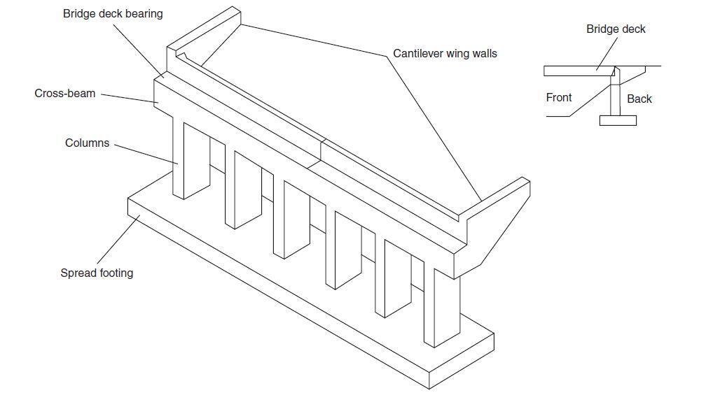
This type of abutment (shown below) is composed of two or more buried columns supported on a single foundation slab and topped by a cill beam to support the deck structure. To minimise long-term settlement, the backfill must be carefully compacted around the columns since it overflows between the legs.
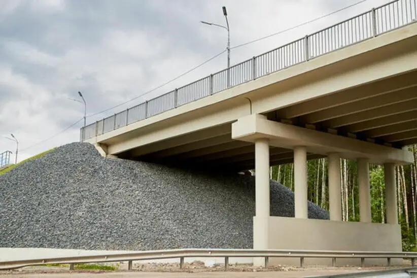
It is frequently employed in embankment situations where a suitable foundation can be located at the original ground level. In this situation, it might be a more affordable option than a bankseat that is supported by piles pushed through the embankment fill. Figure 9 depicts a typical spill-through abutment bridge, however the completed embankment makes it impossible to see the abutment’s legs.
Since very few field tests have been conducted to ascertain the long-term movements and ground pressures on the subterranean structure, design assumptions for this sort of abutment vary substantially. Assuming full active earth pressure across the whole width of the abutment, regardless of the soil that pours between the columns, is one conservative, straightforward design strategy. While the fill between the columns may arch or experience “drag effects,” the columns and cill beams are typically thought of as being loaded by active earth pressure.
Integral Abutments
Conventional bridges typically include expansion joints and bearings inserted between the superstructure and the abutments to account for relative movement and prevent temperature-induced strains from building up between the superstructure and abutments. These expansion joints and bearings, however, may result in significant maintenance issues.
The concept of physically and structurally joining the superstructure and abutments to produce what is known as an integrated bridge has gained popularity as a result of the issues with conventional bridges that feature joints and bearings. All of the aforementioned issues with joints and bearings are prevented by integral bridges.
The abutments are however compelled to move away from the soil they hold onto when the temperature drops and the deck contracts (for example, in the winter), and towards the soil when the temperature rises and the deck expands because of the integral connection between the superstructure and the abutments (e.g. in the summer). Because of this, the soil behind the abutment experiences temperature-induced cyclic loading from the abutment, which might result in substantially higher earth pressures than originally intended.
Reinforced Earth Abutments
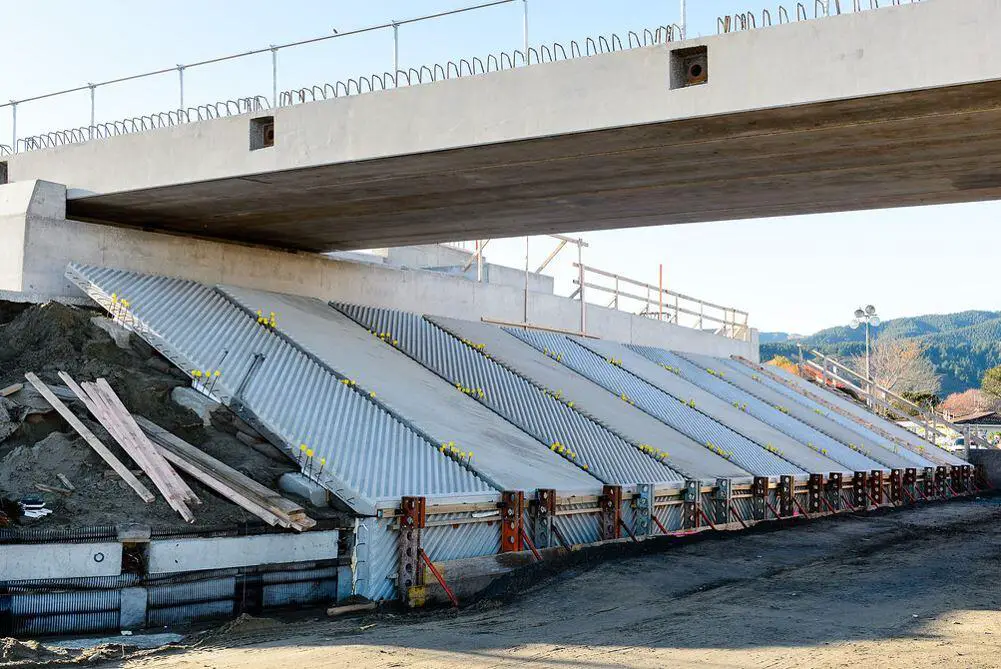
Modular facing panels, often made of pre-cast concrete, earth fill, and soil reinforcement make up a reinforced earth wall. The wall is constructed by repeatedly performing a series of tasks at various levels, including installing face panels, putting earth fill in place and compacting it, laying reinforcements (geotextiles), and putting more earth fill in place and compacting it. Until the necessary height is attained, the processes are repeated.
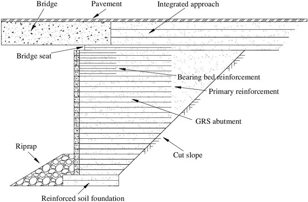
The facing panels shape the surface, enabling the construction of nearly vertical walls, and the finished wall is able to resist lateral pressure through friction along the reinforcing. When a bankseat is built on top, reinforced earth can be used as part of the abutment. To minimise any local loading effects that could result in local deformations on the face of the wall in this situation, the bankseat is often positioned back from the top of the wall.
Reinforced earth walls are widely used in conjunction with other types of abutment structures to create affordable retaining walls around bridge approaches.
Abutment Foundations
Most abutments are generally supported by either spread or piled foundations. Three issues need to be considered in the choice of foundation:
- the available bearing capacity of the undisturbed natural soil at the site;
- the settlement that the foundation will undergo (and impose on the superstructure); and
- the tolerance of the abutments, deck, etc., to the expected differential settlements.
Most of the time, when the soil’s bearing capacity is sufficient to sustain a spread footing with minimal settlements, this will be the most cost-effective laying alternative. If rock is present at the founding level, this will necessarily result in a spread footing solution. Most dense sands, granular soils, or stiff clays will give appropriate bearing capacities for spread footings.
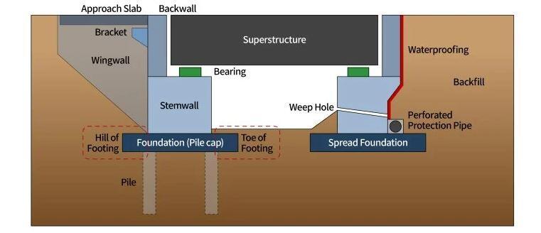
When soft compressible soils are present or the abutment is situated at the top of a steep embankment, piles are typically used. If a top-down strategy is used for building bridges in cutting, the use of piling can streamline the process.
In many cases, it might be more cost-effective to remove any soft material and replace it with well-compacted granular material or mass concrete rather than using pilings if a suitable soil or rock is present within a reasonable depth of the founding level.
Although differential settlement is difficult to predict with any degree of certainty, past experience indicates that it might be as much as two-thirds of the maximum total projected settlement. While spread foundations may be adequate for some sites based on their bearing capacity, their size frequently results in comparatively substantial overall settlements when compared to the settlements that a well-designed pile foundation is likely to encounter (typically less than 10mm at working load). The ability of the deck structure to contain the anticipated differential settlements may therefore dictate the choice of foundation method.
Abutment Approach Slab
One can anticipate that the embankment fill next to the deck will settle significantly (and perhaps a few per cent of the fill height). Without specific precautions, the intended vertical alignment of the highway pavement would be disrupted, which will result in a bad ride quality for vehicles on the approaches to bridge decks. There are two methods that could be used: a granular wedge next to the abutment or structural run-on (approach) slabs.
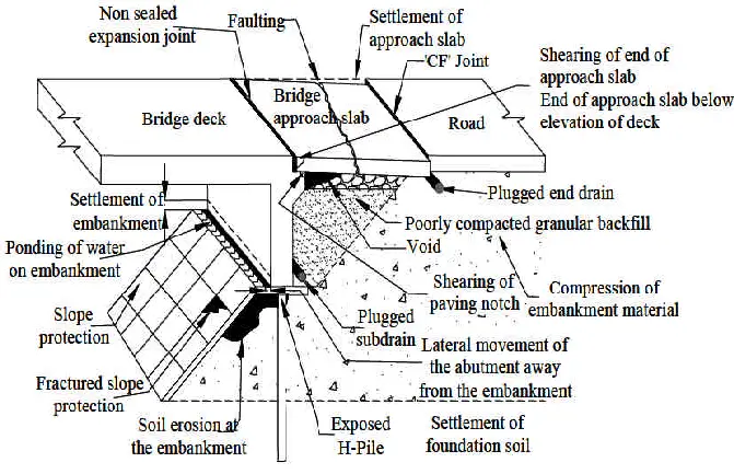
An approach slab will provide a smooth transition between the relatively flexible approach pavement and the nonflexible bridge superstructure by bridging across the settling fill immediately behind the abutment. However, for integral abutments backfilled by granular materials, the backfill will become gradually compacted under horizontal cyclic loading from the abutment and a void will form under the run-on slab, which may cause damage to the slab under traffic load if it has not been designed for this case.
Design of Abutments
The primary function of an abutment wall is to transmit all vertical and horizontal forces from a bridge deck to the ground, without causing overstress or displacements in the surrounding soil mass. The abutment wall also serves as an interface between the approach embankments and the bridge structure, so it must also function as a retaining wall.
The type of the bearing supports, if any, determines how much a bridge deck and an abutment wall interact with one another. Integral abutments are becoming more popular since they eliminate the need for additional bearings and the associated maintenance costs. It is simple to idealise the impact of bearing type, end fixity, or free supports throughout the design phase. It is more difficult to predict the impact of ground movements brought on by settlement, mining subsidence, or earth tremors, and these impacts must be taken into account specifically for a given structure.
The primary vertical loading acting on an abutment is due to the dead load and live load reactions from the bridge deck. Additional loading arises from the self-weight of the abutment, earth pressure, wall friction between the backfill and the abutment, and live loading immediately behind the abutment.
Traction and braking forces due to live loads on the deck are carried at the fixed bearings and may represent a substantial overturning moment on a tall abutment. Although these forces are applied to localised areas of the deck, they can usually be treated as a uniform load across the width of the abutment.
Loadings on Abutments
A number of actions are possible on abutments which must be thoroughly accounted for in the designs. Some of the actions are as follows;
Soil Loading
The earthfill retained at the back of abutments exert earth pressure as typical for retaining walls. This may be accompanied by water hydrostatic pressure if adequate drainage is not provided at the back of the wall. In a situation where a wall can move by tilting or sliding and the backfill is a free draining granular material, active pressures are assumed.
Vehicle loading (surcharge)
In the simplest case, for example a distributed load (q kN/m2) at the ground surface, such as an HA loading, an additional stress equal to Kaq can be added to the earth pressure assumed on the back of the abutment. For the design of highway bridges, a live load surcharge of 10 kN/m2 for HA loading and 20 kN/m2 for 45 units of HB is often used. For rail loading either a UDL of 150 kN/m along each track, applied over a 2.5m width, or an RU and RL surcharge of 50 kN/m2 and 30 kN/m2 respectively is taken over the track area.
Compaction Pressure
The application of compaction plant, such as heavy vibrating rollers, to abutment backfill in layers leads to temporary but quite large increases in both vertical and horizontal stress within the fill. Some of these stresses remain locked into the fill, and can give considerable additional lateral loading on a cantilever abutment, particularly over the depth just below the top of the wall.
Swelling Pressure
Compaction of cohesive fill produces even greater increases in lateral earth pressures than in granular fill, of the order 0.2–0.4 times the undrained shear strength. But for such clays the more significant issue is likely to be lateral swelling pressures. For clays placed relatively dry, a relaxation in lateral stress has been observed immediately after compaction.
However, as rainwater enters the fill, swelling starts to occur. In situ determinations of the average lateral stresses within a 6m high abutment backfill of London clay showed that horizontal total stresses rose up to 180 kPa near to the centre of the embankment, and up to 70 kPa close to the wing walls. Another pilot-scale experiment observed average lateral pressures on a 3m high wall of the order of 100 kPa. Given that these figures are of the order of many times higher than the commonly assumed equivalent fluid pressure, it is suggested that cohesive backfill should not be used behind abutments.
Effects of seasonal deck expansion and contraction
Longitudinal movements in the bridge deck due to creep, shrinkage and temperature changes cause forces at bearing level on non-integral abutments. The magnitude of these forces depends upon the shear characteristics or frictional resistance of the bearings. The coefficient of friction of most bearings lies in the range fi = 0.03–0.06. The frictional force is derived from the nominal dead load and the superimposed dead loads on the deck.
Integral abutments do not have bearings, and therefore the backfill they support is subjected to seasonal increases and decreases in horizontal strain. The deck is stiff relative to the backfill and the soil provides insufficient restrain to prevent movement.
Load Combinations for Abutments
BD 30.87 – UK Standard
Case 1:
Backfill + Construction surcharge
Wall backfilled up to bearing shelf level only.
Case 2:
Backfill + HA surcharge + Deck dead load + Deck contraction
Case 3:
Backfill + HA surcharge + Braking behind abutment + Deck dead load
Case 4:
Backfill + HB surcharge + Deck dead load
Case 5:
Backfill + HA surcharge + Deck dead load + HB on deck
Case 6:
Backfill + HA surcharge + Deck dead load + HA on deck + Braking on deck
(Not applied to free abutment if sliding bearings are provided)
Load Combinations (European Standards)
Case 1:
Backfill + Construction surcharge
Case 2:
Backfill + Normal Traffic Surcharge + Deck Permanent load + Deck contraction/shrinkage
Case 3:
Backfill + Normal Traffic Surcharge + Deck Permanent load + gr1a on deck
Case 4:
Backfill + SV/100 and SV/196 Surcharge + Deck Permanent load + gr1a (frequent value) on deck
Case 5:
Backfill + Normal Traffic Surcharge (frequent value) + Deck Permanent load + gr5 on deck
Case 6:
Backfill + Normal Traffic Surcharge (frequent value) + Deck Permanent load + gr2 (ψ1LM1 with braking on deck)
(Braking not applied to free abutment if sliding bearings are provided)
Case 7:
Backfill + Deck Permanent load + gr6 (LM3 with braking on deck)
(Braking not applied to free abutment if sliding bearings are provided)
Stability of Abutments
The stability of an abutment should be checked for three basic modes of failure:
- sliding;
- overturning;
- overall instability.
Sliding
When passive resistance in front of the toe can be relied upon, the minimum factor of safety taken in design is normally 2.0. If the passive pressure contribution is neglected, then a minimum factor of safety against sliding is usually 1.5. A shear key is sometimes provided in the base slab to mobilise greater soil resistance when otherwise the resistance to sliding is inadequate.
Overturning
Overturning is checked by taking moments about the toe when the most adverse load combination is acting on the structure. A minimum factor of safety of 2.0 is normally adopted providing the resultant reaction lies within the middle third. If there is ‘tension’ in the bearing pressure at the heel, then a higher factor of safety may be used as a further precaution against failure.
Overall instability
A slip circle analysis is essential for a bankseat form of construction and may be necessary for other types of abutment when the soil strata well below the structure is weaker than the soil layers at foundation level. Where soil strengths are based on tests, then a minimum factor of safety would be 1.5. Particular care is needed during construction if an intermediate pier foundation is being excavated at the toe of a cutting slope, when there is a bankseat positioned at the top.
Structural Design of Abutments
The structural design of abutments involves the selection of the proper thickness of the wall (stem) and base, and selection of the proper size and spacing of reinforcements to prevent ultimate and serviceability limit state failure.
Base Design
A base slab’s toe is made to withstand the highest ground forces pressing on the base, while some relief can be obtained from the toe’s self-weight and any added fill. The heel must be made to withstand upward ground pressure as well, however in this instance, fill, live load surcharge, and self-weight can generate high loading circumstances that can reverse the shears and moments that follow. The foundation slab may be supported by piles, in which case the predicted loads in each pile would take the place of the bearing pressures.
Wall Design
The stem of an abutment wall is designed to withstand the shears and bending moments caused by horizontal forces, as well as the bending imposed by the deck in the case of integral bridges. Since direct stresses from vertical loads are typically relatively minimal, they can be disregarded when designing walls. At the root of torsion blocks on horizontally cantilevered wing walls, significant in-plane strains can develop.
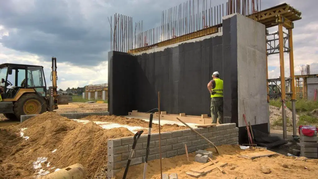
While for integral bridges the top of the wall and connection with the deck can also be crucial, the key section for moments and shear forces occurs at the root of the wall in the case of simple vertical cantilever walls. Due to traction and braking effects, concentrated horizontal stresses may exist at bearing level as well as at the back of the curtain wall. Calculating the bending moments in the wall typically involves distributing these loads vertically.

