Pile caps are rigid plate structures that are used to transfer superstructure load from columns to a group of piles. They are usually subjected to bending and shear forces, and shear considerations usually govern the thickness design of pile caps. The three main approaches that are used in the analysis of pile caps are;
- Truss Analogy
- Bending analogy, and
- Finite element analysis
While truss analogy and bending theory can be easily carried using quick manual calculations, finite element analysis usually require the use of computer models. In this article, we are going to explore the potentials of Staad Foundation Advanced Software in the analysis and design of pile caps.
Read Also…
Design of pile foundation system for bridge piers
Structural Aspects of Pile Foundation Design
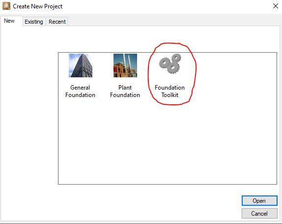
A quick design of pile caps can be done on Staad Foundation Advanced using the Foundation Toolkit option. This approach does not require importing models and can be used for quick stand-alone design when the column load and geotechnical parameters of the soil are available. To use this option, launch the ‘Staad Foundation Advanced‘, click on ‘New Project‘, and select ‘Foundation Toolkit‘ labelled as shown below.
Step 1: Launch the foundation toolkit
Step 2: Create Pile Cap Job
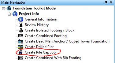
When the Foundation Toolkit opens, go to ‘Main Navigator‘, and from ‘Project Info‘ drawdown list, select ‘Create Pile Cap Job‘ as shown below.
Step 3: Select design code, units, and pile layout
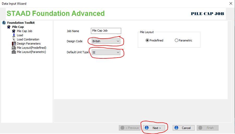
When the ‘Pile Cap Job’ is launched, select the desired code of practice, unit, and click ‘Next’. The pile layout can be left as predefined.
Step 4: Define the load
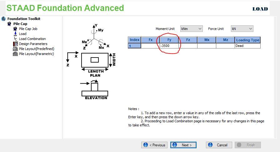
On clicking ‘Next’, the dialog box for load comes up. Make sure that the unit is consistent as desired, and for this exercise, I am applying a factored column load of 3500 kN. If there are other forces such as moment and shear coming from the column, you can define them also.
Step 5: Define Load Combination
Since we are dealing with an already factored load, select ‘User Defined‘ from the drawdown list of load combination. If you have defined dead load, live load, wind load etc in Step 4, you can select the desired code of practice for the combination of the loads. Since I defined my factored load as dead load, I assigned a factor of 1.0 to dead load at ULS and SLS (actually I am not interested in SLS in this design). Then click ‘Next‘
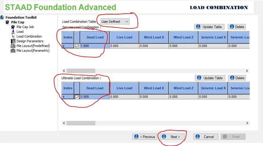
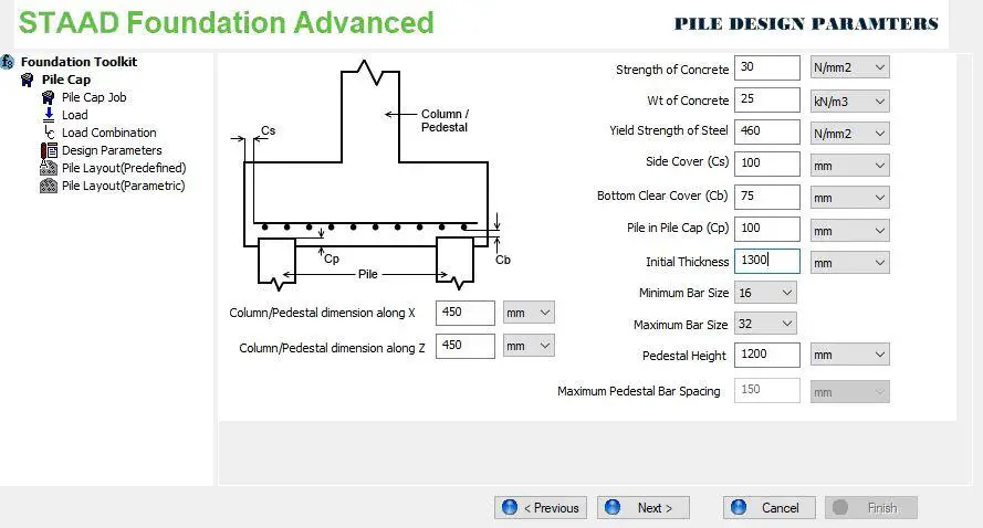
Step 6: Define the design parameters
In this case, the column dimensions are taken as 450 mm x 450 mm, and the thickness of the pile cap was taken as 1300 mm. Other design parameters specified are as shown below.
Read Also…
Manual Design of Beam and Raft Foundation
Solved Example on Elastic Settlement of Shallow Foundations
Step 7: Select pile arrangement
The diameter of the pile was selected as 750 mm, with a spacing of 2250 mm. The safe working load of the pile was taken as 900 kN. You can also input the uplift and lateral load capacity of the pile. The edge distance is taken as (diameter of pile/2 + 150 mm) – where 150 mm is the overhang from the edge of the pile to the edge of the pile cap. Then click on ‘Calculate‘.
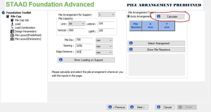
This brings the possible pile arrangements based on the safe working load and the superstructure load. For this tutorial, the arrangement below was adopted. The simple idea behind it is simply (Column load/pile safe working load). Note that for practical purposes, serviceability limit state load should be used when selecting the number of piles. Then click ‘Ok‘ and ‘Next‘.

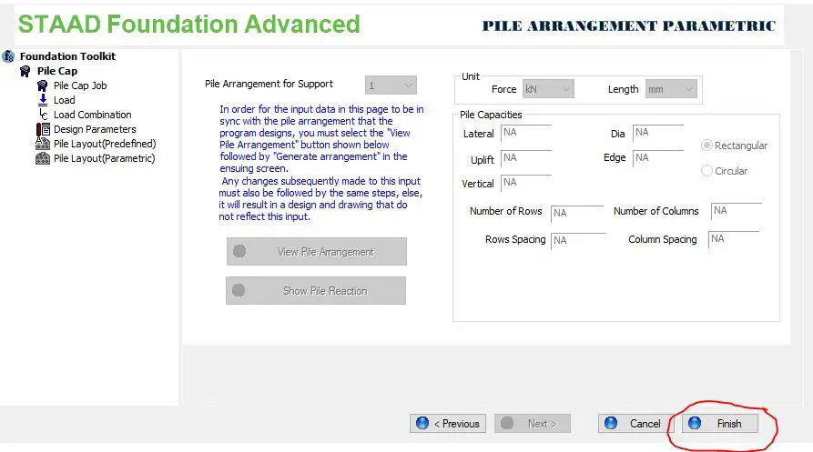
Step 8: Finish the model
Step 9: Carry out the Design
Clicking ‘Finish‘ returns you to the ‘Main Navigator‘ page, where you can click on ‘Design‘ to carry out the design of the pile cap.

Step 10: View the output
The output page is where you can view the geometry drawing, details and schedule drawing, calculation sheet, and graphs.

The design approved the 1300 mm thick pile cap provided, and provided Y16@100 mm c/c reinforcement. You can go ahead and print the calculation sheet which you can download below.
Thank you for visiting Structville Today, and God Bless You
#1. Which of the following is not a primary ingredient used in production of concrete?
#2. 60 to 75% of concrete is made up of?
#3. Which of the following is not an advantage of reducing water content in concrete?
#4. The ease of placing, consolidating, and finishing freshly mixed concrete is called?
#5. Bleeding in concrete is not caused by one of the following?
#6. The chemical reaction between cement and water is called?
#7. If hardened concrete is saturated again after a drying period, strength will increase
#8. 7 days compressive strength of concrete is often estimated to be _____ of the 28 days strength
#9. Which of the following affects the compressive strength of concrete?
#10. Compressive strength of concrete can be used as an index of the flexural strength, direct tensile strength, and spliting tensile strength
#11. The capability of concrete to hold back water without visible leakage is called?
#12. Additional deformation in concrete due to sustained stress is called?
#13. When permitted to dry completely, concrete will?
#14. Which of the following will not affect the amount of shrinkage in concrete?
#15. Which of the following can be used to control cracking in concrete?
#16. The process by which carbon dioxide from the air penetrates concrete and reacts with hydroxides is called?
#17. One of the following is not a method of protecting steel from corrosion?
#18. Water that has not reacted with cement paste in a cementitious mixture is known as?
#19. For complete hydration of portland cement, about ____ of water is needed
#20. The overall particle size distribution of cement is called?
#21. The ability of a hardened cement paste to retain its volume is known as?
#22. The time that elapses from the moment water is added to cement until the paste ceases to be fluid and plastic is called?
#23. The average particle density of portland cement is usually taken as?
#24. Which test is used to measure the consistency of concrete?
#25. The process of measuring concrete mix ingredients by either mass or volume and introducing them into the mixer is called?
#26. The minimum mixing time (using concrete mixer) usually required to each cubic metre of concrete is?
#27. The tendency for coarse aggregate to separate from sand-cement mortar is called?
#28. Which of the following is not a method of curing concrete?
#29. The recommended maximum water/cement ratio for water retaining structures is?
#30. Choose the odd one out
#31. The volume of fresh concrete produced from known quantities of component materials is known as the?
#32. Which of the following is not true about concrete?
#33. According to ASTM standard, which of the following is regarded as a general use cement?
#34. Which chemical component of cement plays the biggest role in high heat of hydration?
#35. For a material to qualify as a pozzolan, the alumina and silica oxides combined should be up to?
#36. Vicat needle is popularly used for testing?
#37. Excessive impurities in mixing water of concrete can cause the following except?
#38. The bulk unit weight of coarse aggregates used in the production of normal weight aggregate is expected to range from?
#39. In concrete production, aggregates passing 5 mm sieve (3/16″) and retained on No 200 sieve is regarded as?
#40. The moisture states of aggregates in which during mixing they will neither absorb any of the mixing water added nor contribute any of their contained water to the mix is called?.
#41. Which of the following properties of coarse aggregate is not required for mix design?
#42. Shape of aggregate cannot influence strength of concrete
#43. Water reducing admixtures are popularly called?
#44. Prolonged mixing of concrete can lead to the following except?
#45. Concrete should be placed in ______?
#46. At any degree of hydration, the porosity of any cement paste depends on?
#47. Lean concrete is considered to be?
#48. At a constant water/cement ratio, lean concrete mix will lead to?
#49. The interface between aggregate and cement paste is called?
#50. The coefficient of expansion of concrete is largely influenced by?
Results
Congratulations! You passed the concrete test. You can share your result on your social media and encourage you friends to try.
Oopps! You did not satisfy the minimum requirement of 60% score.


