Understanding sign conventions is one of the most important aspects of structural analysis. As a matter of fact, it is always a pausing point for all civil engineering students being introduced to structural analysis for the first time. If you do not understand sign conventions properly, it will be difficult to make significant progress in mastering structural analysis calculations.
The three most prominent internal forces in structural analysis calculations are the bending moment, shear force, and axial force. It is very common for people to define and state their sign convention before proceeding with any structural analysis problem. This is mainly due to variations in the selection of positive and negative coordinates.
For instance, most Indian and American textbooks will adopt the conventional cartesian coordinates system, and plot all positive bending moment upwards, and negative moments downwards, while most British and Scandinavian textbooks will plot positive moment downwards, and negative moments upwards.
However, it is important to note that what matters most in sign conventions is consistency. You must be consistent with whatever sign convention you choose to adopt, otherwise, errors will come in. If properly done, the values will remain the same, but the signs will differ.
Is there any standard approach?
I will prefer to answer yes because it is more appropriate to plot the bending moment diagram in the tension zone/fibre/face of a structural member. This is especially important in reinforced concrete structures where there is a need to provide tension reinforcement.
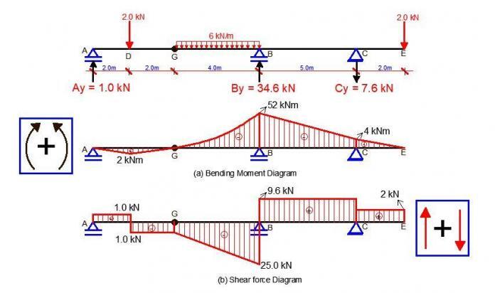
For instance, if you consider a continuous beam subjected to uniformly distributed load with the bending moment diagram plotted in the tension zone, you can easily point out and provide bottom reinforcements at the spans, and top reinforcements at the supports.
See an example below;
From the figure above, you can see the consistency of the bending moment diagram with the typical arrangement of the reinforcement. This is because the bending moment diagrams were plotted in the tension zone, and of course, it means that the positive moment was plotted downwards. However, if the cartesian coordinates system was strictly followed, we would have been reversing the placement of the reinforcements with the bending moment diagram.
The same thing also applies to frames. You should plot your bending moment diagram in the tension zone of the members of the frame.
However, there are procedures that you must follow in your calculations in order to be consistent. By consistent, what I mean is that your positive bending moment will imply a sagging moment, while negative will mean a hogging moment. With this, you can plot your diagram directly as you have calculated, without having to interchange signs.
The summary of the procedures is given below.
Sign Convention for Beams
Bending moment
When you are coming from the left-hand side of the structure, all clockwise moments are positive and vice versa. When you are coming from the right-hand side of the structure, all anti-clockwise moments are positive and vice versa.
Shear force
When you are coming from the left, upward forces are positive, while downward forces are negative. When you are coming from the right, downward forces are positive, while upward forces are negative.
Axial force
Compressive axial forces are negative, while tensile axial forces are positive.
All you have to do is to look at the direction of the force. When coming from the left-hand side of beams, axial forces pointing towards the right means that the beam/section is in compression. When coming from the right, axial forces pointing towards the right means that the beam/section is in tension and vice versa
Sign Convention for Frames
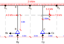
For the sign of convention of frames, we are going to use the frame below as an example.
Bending moment
When coming from the left-hand side, all clockwise moments are positive, and anti-clockwise moments negative. All you have to do is to look at the point where you are taking your moment and observe the nature of rotation the force will produce. This is valid for both vertical and horizontal forces.
When coming from the right, all anti-clockwise moments are positive.
For frames, we plot positive moments inside, and negative moments outside the frame. See the example below.
Shear force
When coming from the left, upward vertical forces are positive and downward forces are negative. For horizontal forces on columns, forces pointing towards the right produce negative shear forces.
When coming from the right, downward vertical forces are positive, while upward vertical forces are negative. Horizontal forces on columns pointing towards the left will produce positive shear forces.
We plot positive shear forces outside the frame, and negative shear forces inside the frame.
Axial Force
When coming from the bottom of columns, upward vertical support reactions means that the column is in compression whether you are coming from the left or right.
When coming from the right-hand side of beams, forces pointing towards the right means that the beam is in compression and vice versa.
To me, you are free to select any location to plot your axial forces. Some people draw axial force diagrams to coincide with the centerline of the structure. In the classroom where I was trained, we draw negative axial forces outside the frame, and positive axial forces inside the frame. So it’s your choice to make.
I hope you find this article useful. If so, I will like you to share it.
Continue to visit Structville and tell your colleagues about us.
Our facebook page is at
www.facebook.com/structville


• One thing that always troubled me was that even with the net, most people still don’t tend to address about the topic in this quality. BIM Consulting
BIM Solutions
BIM Solutions in UK
Shop Drawings Preparation in UK
Fabrication Drawings preparation in UK
MEP F modelling in UK
Interference Analysis in UK
COBie adaptation in UK
Clockwise moments are negative
Please treat indeterminate structure
Opposite the right-hand rule…
Great work Sir
nice